


castleofargh
Sound Science Forum Moderator
- Joined
- Jul 2, 2011
- Posts
- 10,417
- Likes
- 6,026
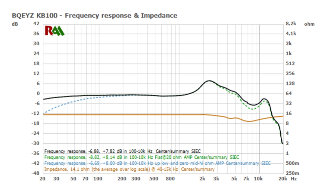
ok but which one is the right measurement?hi everybody. subbed, thanks to the op and other contributors for this amazing thread. nice collection of measurements, very good job, congrats!
i started to measure FR of IEMs last year summer, using iMM-6 + tube and mobile AudioTools. since then, was trying to improve my rig till february; i had to stop to concentrate in other tasks, not related to audio.
now i've read this thread, would like to share my rig evolution, together with some comparing graphs, because it has many coincidences with crinacle's one. hope somebody finds it interesting.
1- iMM-6 + silicone tube. Mobile (input & output) + AudioTools (software).
my mobile input had a terrible bass and treble roll-off, and the output had about 17Ω (http://www.head-fi.org/t/800208/#post_13041235), so had to change the input to my pc soundcard (http://www.head-fi.org/t/800208/#post_13019304), output to a neutral DAC with output impedance lower than 1Ω (like iBasso D14 http://www.head-fi.org/t/800208/#post_12995932, or JDS C5D).
new software was needed. chose REW.
the nozzle of many IEMs wasn't wide enough to be sealed by the tube, so i had to find a good sealing tip to use with every iem. found that one of those used with stetoclips was a good solution.
2- iMM-6 + silicone tube + tip. PC soundcard (input) + iBassoD14 (output DAC) + REW.
compared to pro rigs' measurements, like Tyll's one, found many differences: lows and highs roll-off, different amplitude and location (frequency) of mid and highs peaks, etc.
tried to use the calibration file which came with iMM-6 (it was a joke), and played with the distance from the IEM's nozzle to the mic. that distance resulted to be very important; but even the best distance try showed too many differences to consider a huge effort in calibration of the whole rig.
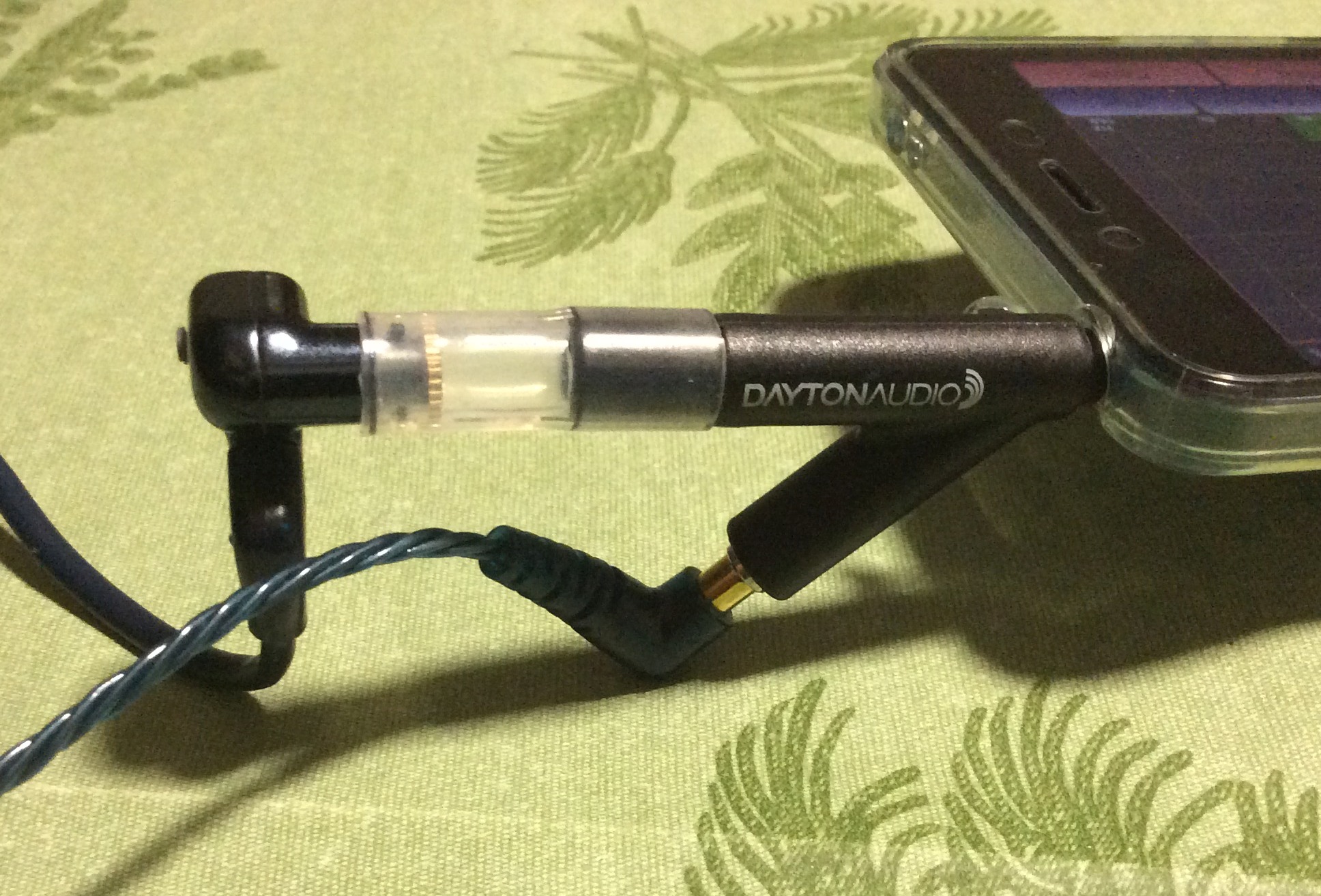
suspected that the diy "coupler" was responsible of the main differences, so tried to make an stainless steel coupler instead, using some vape gear i had around.
3- iMM-6 + DIY SS "coupler".
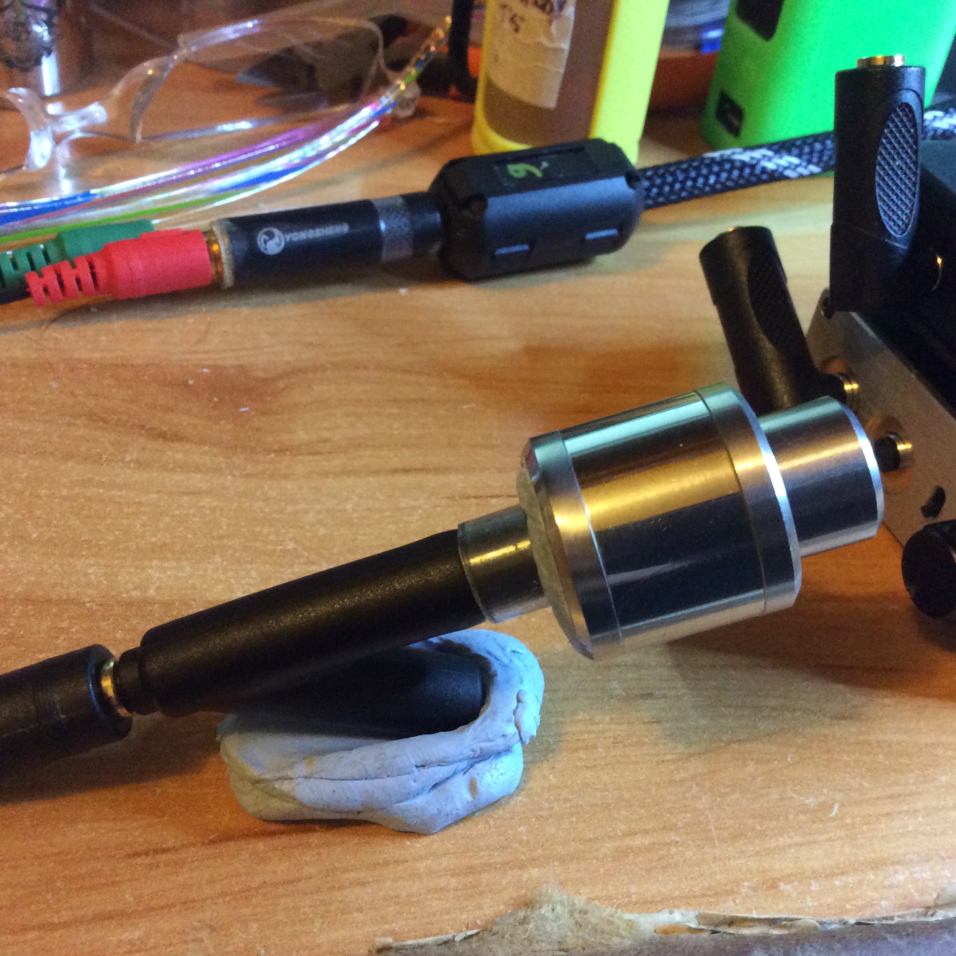
a bit better, but still many differences. the mic fixation to the coupler by using bluetac was not stable enough, and the distance issue was there too.
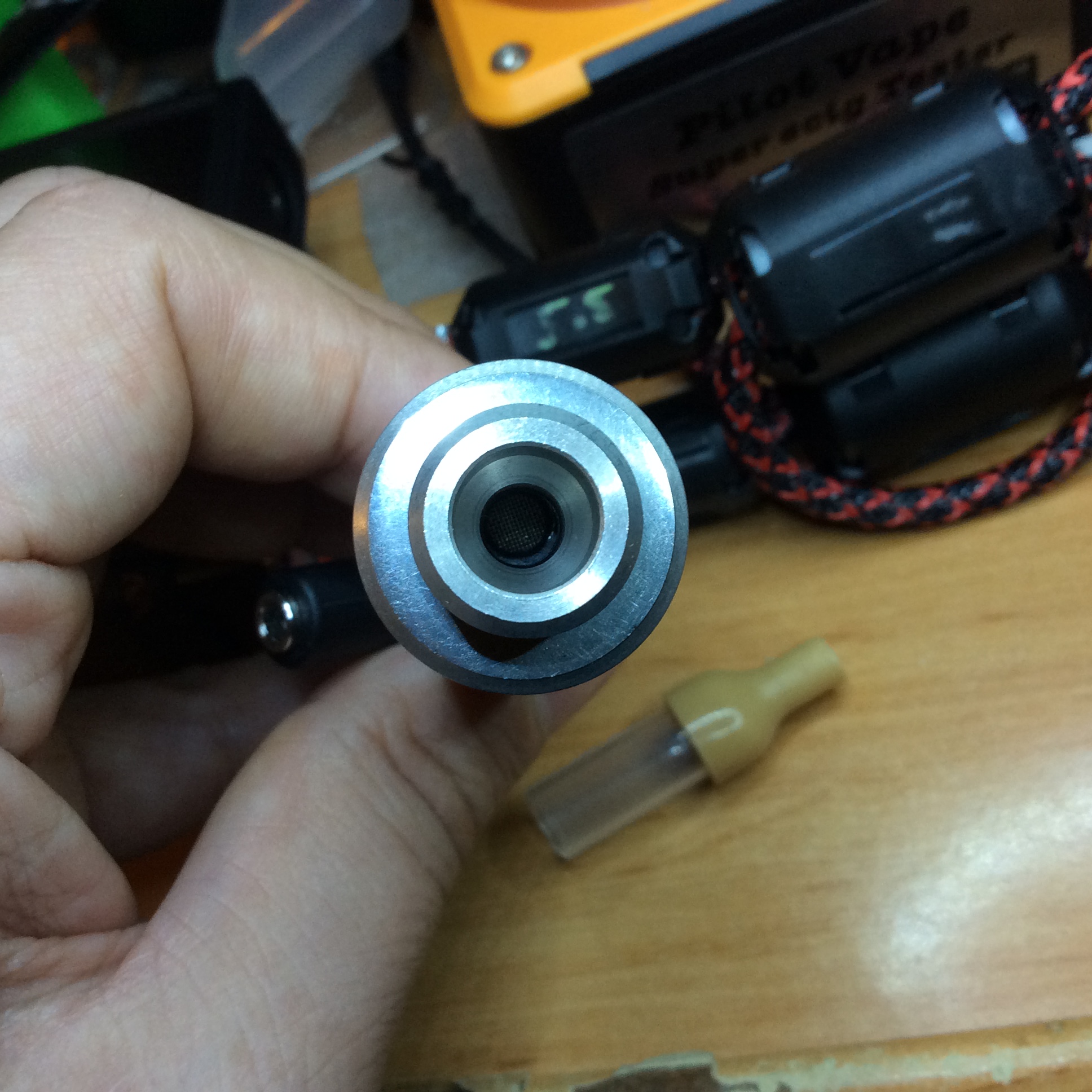
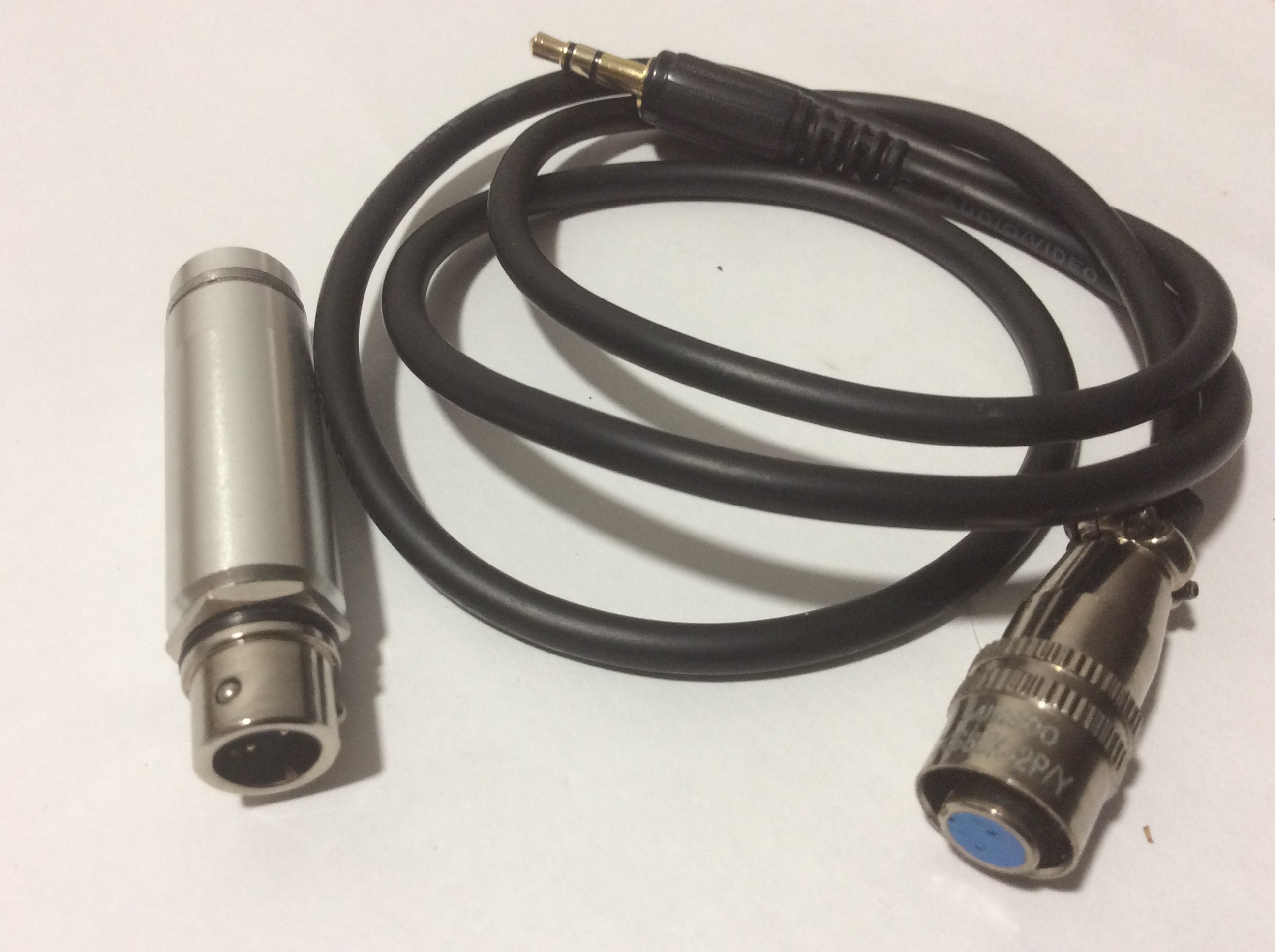
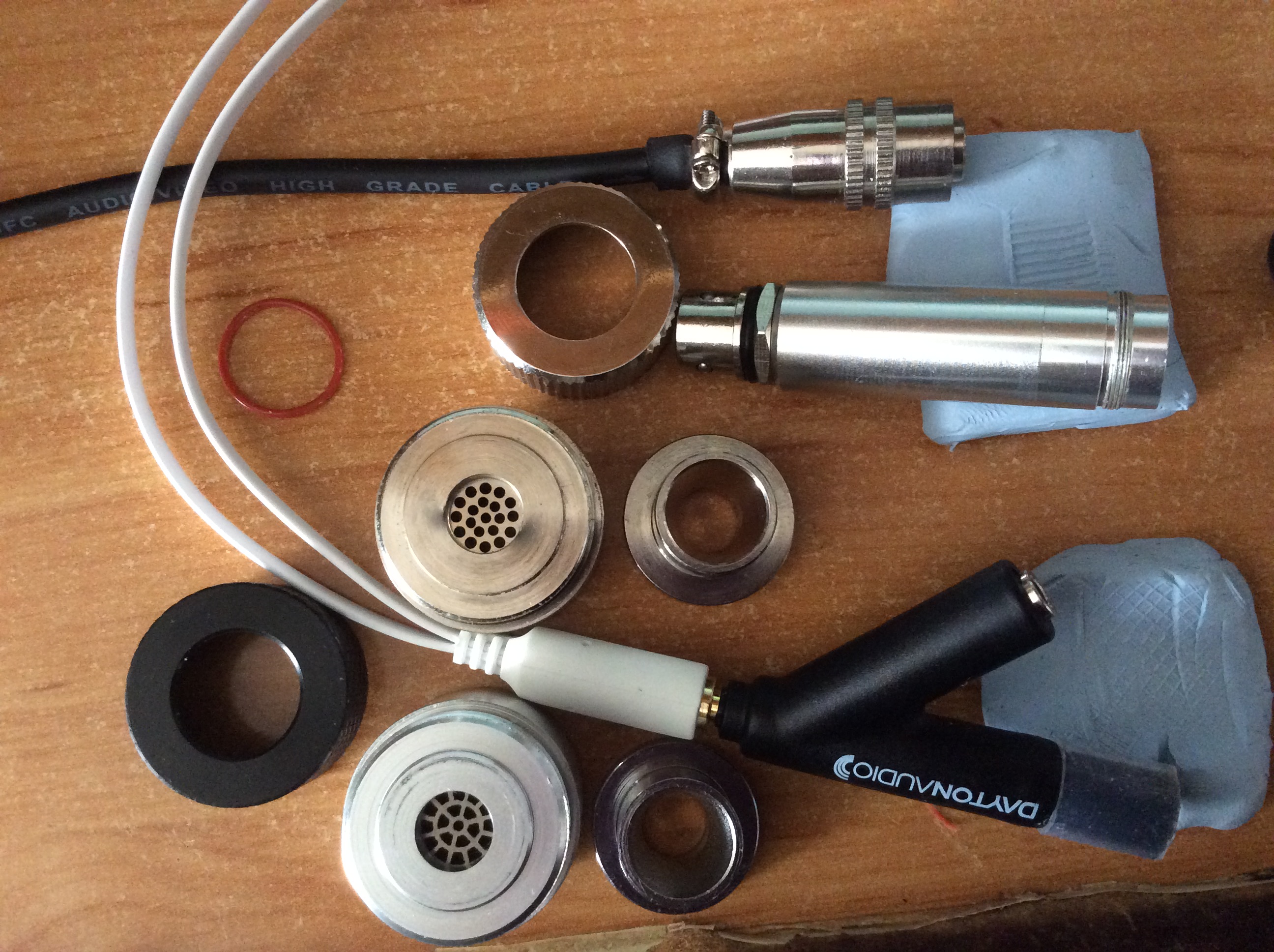
so decided to invest into a chinese iec711 coupler, made by aluminum and other metals, which came with a mic, without any calibration. and also purchased another chinese iec711 coupler after, made by stainless steel and other metals, to check the consistency of these chinese couplers.
4- "cheap" mic + 711 couplers.
couplers:
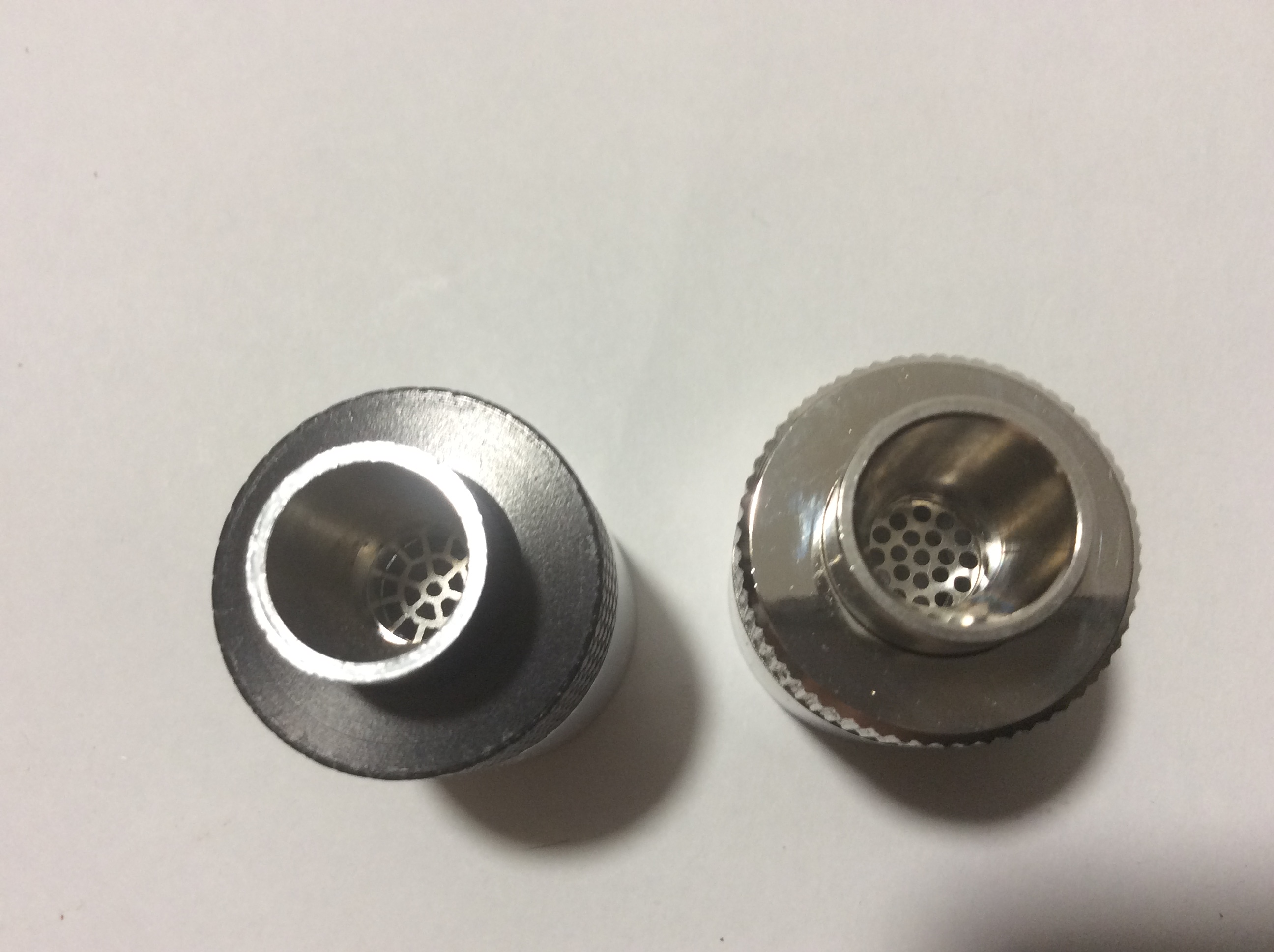
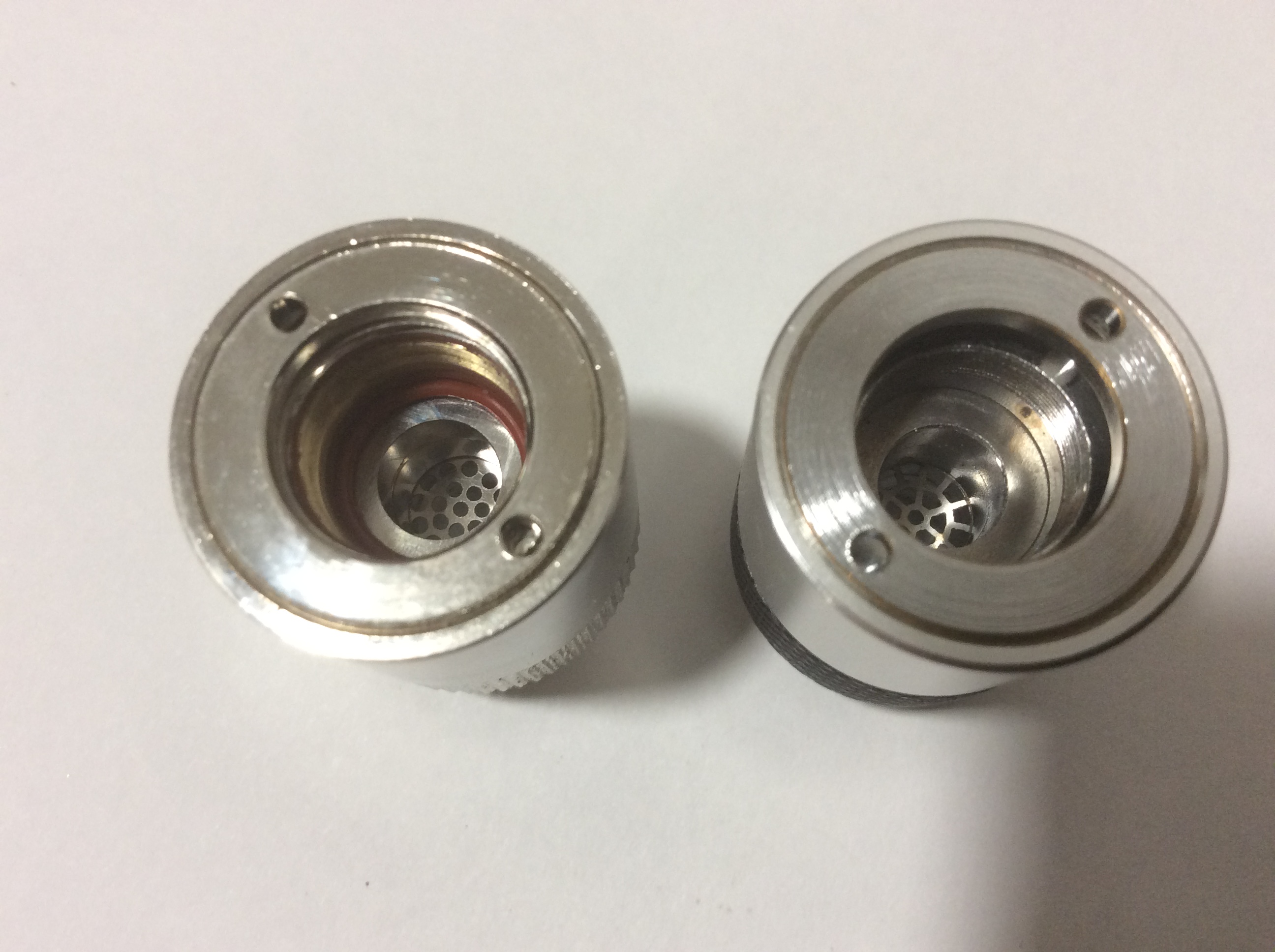
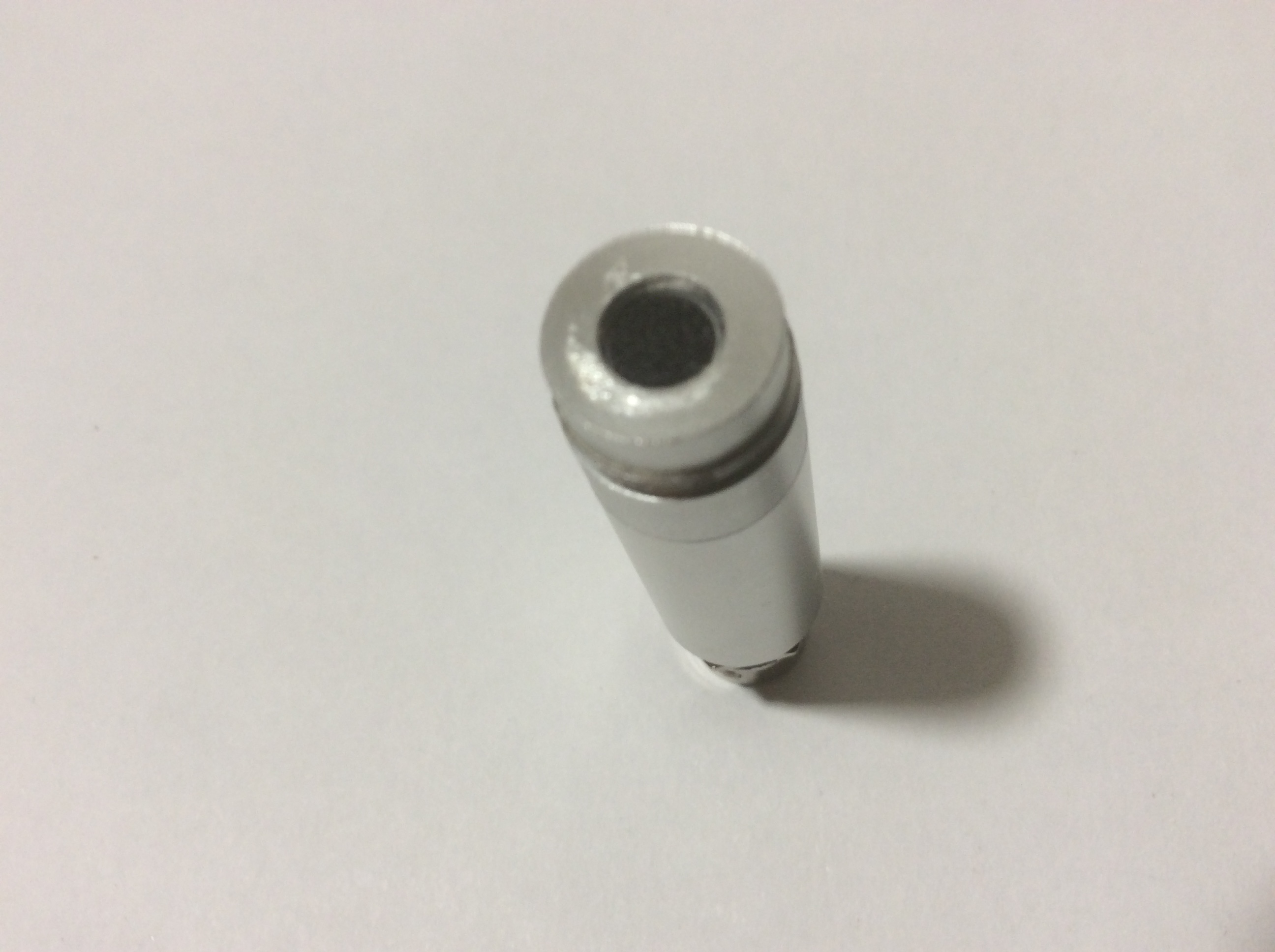
mic which came with aluminum coupler (6mm-1/4"- mic, like imm-06, fixed to a 12mm-1/2"- threaded cillindrical case, to be screwed into the coupler):
found that lows and mids (till 5 or 6KHz) were more accurate this way. but from 5-6KHz, the peaks were better located (frequency) in my old rig (iMM-6 + DIY SS "coupler"), despite of their bigger highs roll-off after 10KHz.
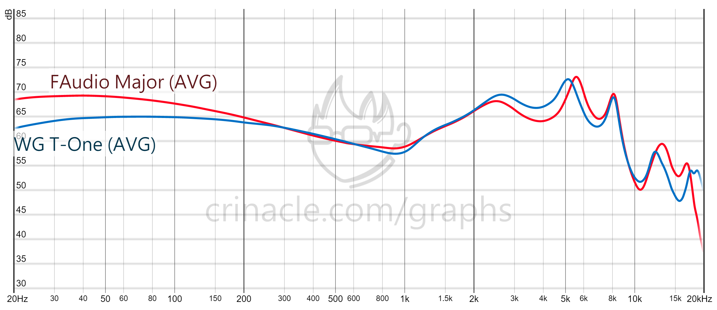
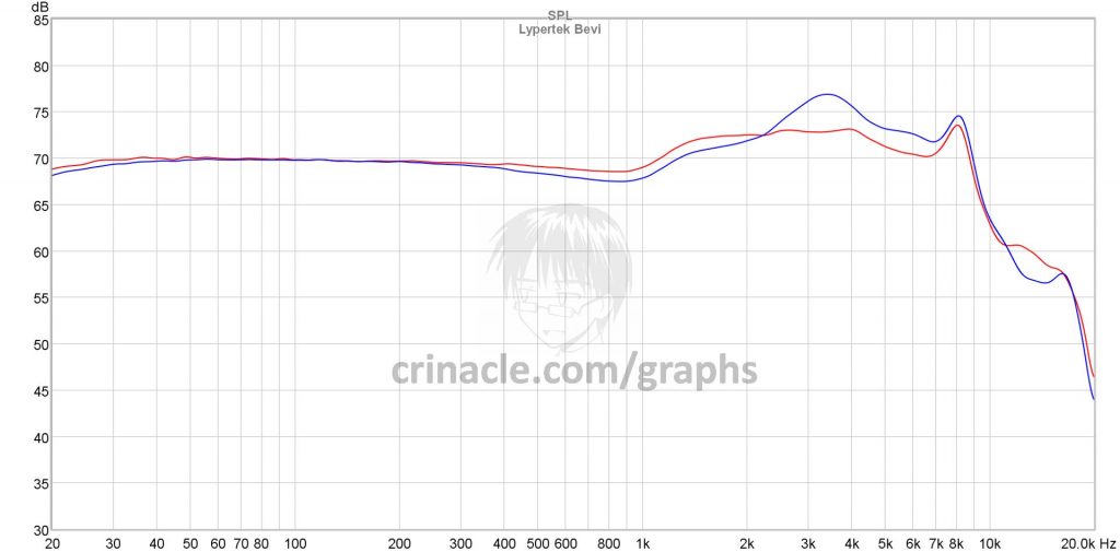
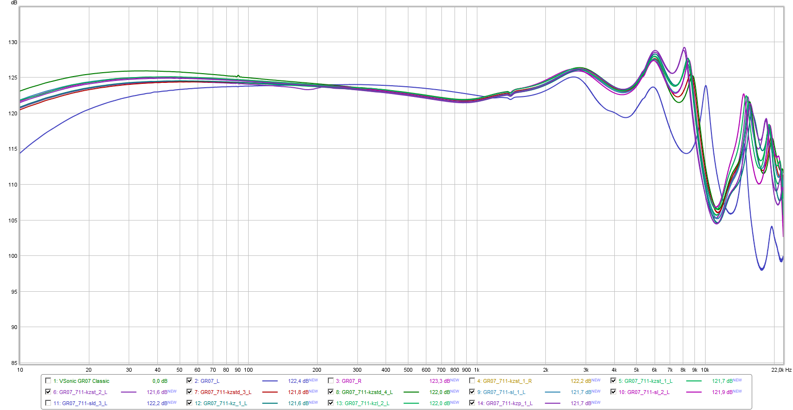
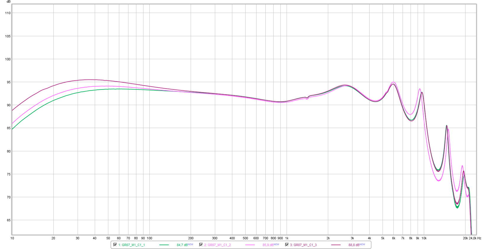
this graph show the difference between them (the similar curves correspond to new rig, rolling tips and varying depth insertion). used VSonic GR07 classic ed.
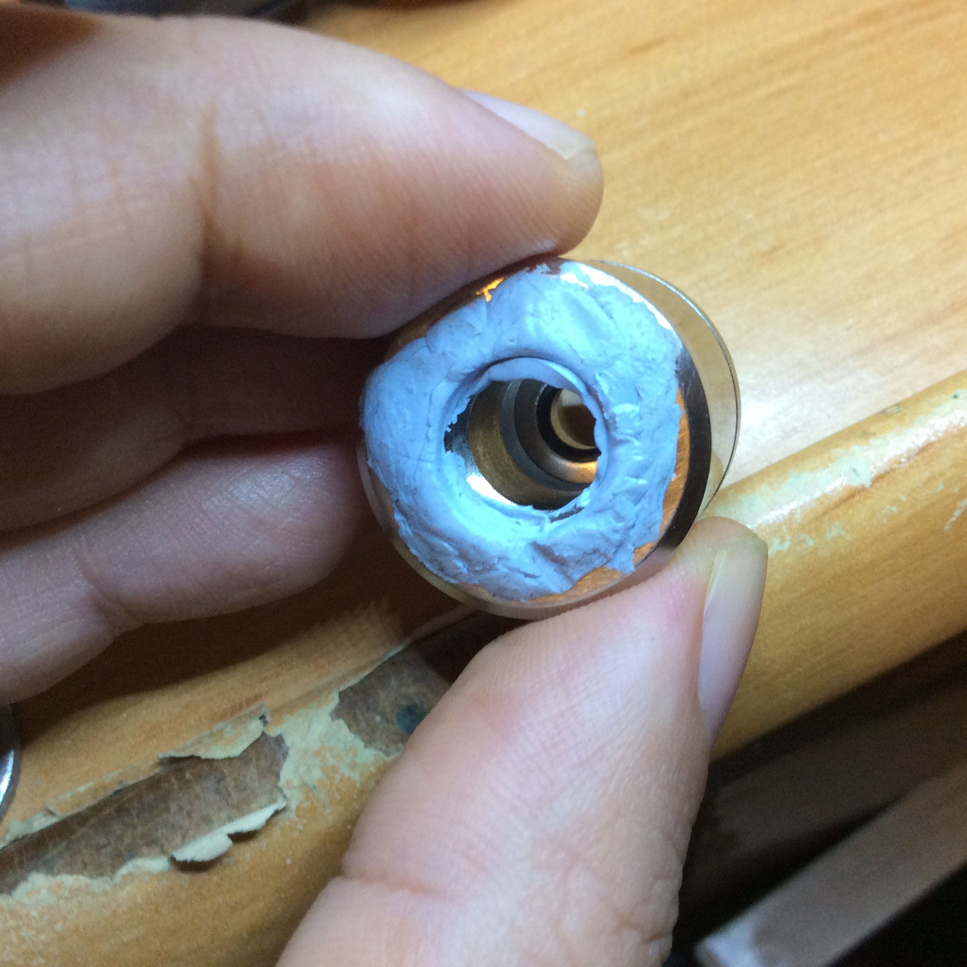
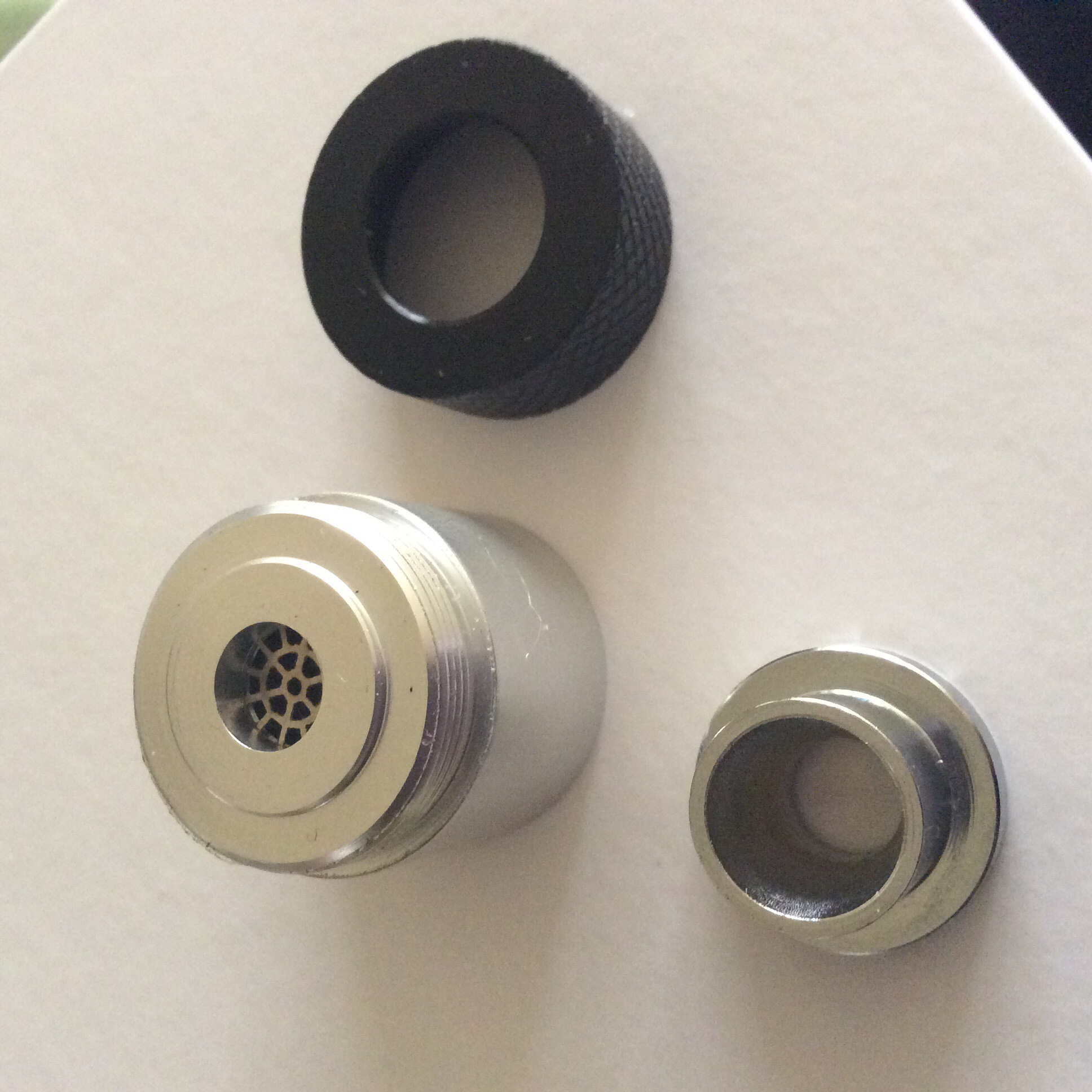
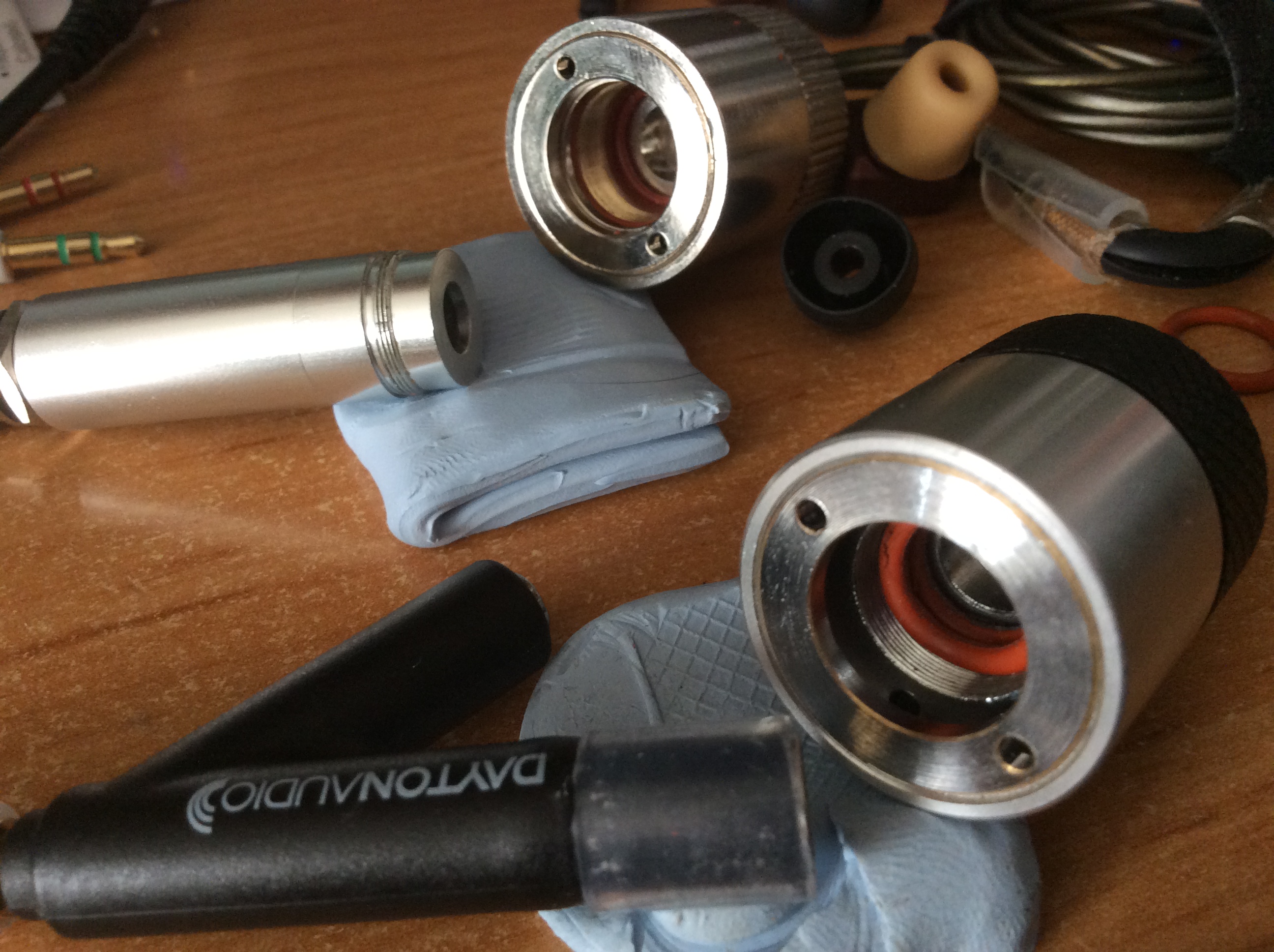
to get better results in highs, i tried to fit the iMM-6 into the 711 couplers, because suspected that the cheap mic was responsible of the frequency offset's mess.
and compared mics and 711 couplers.
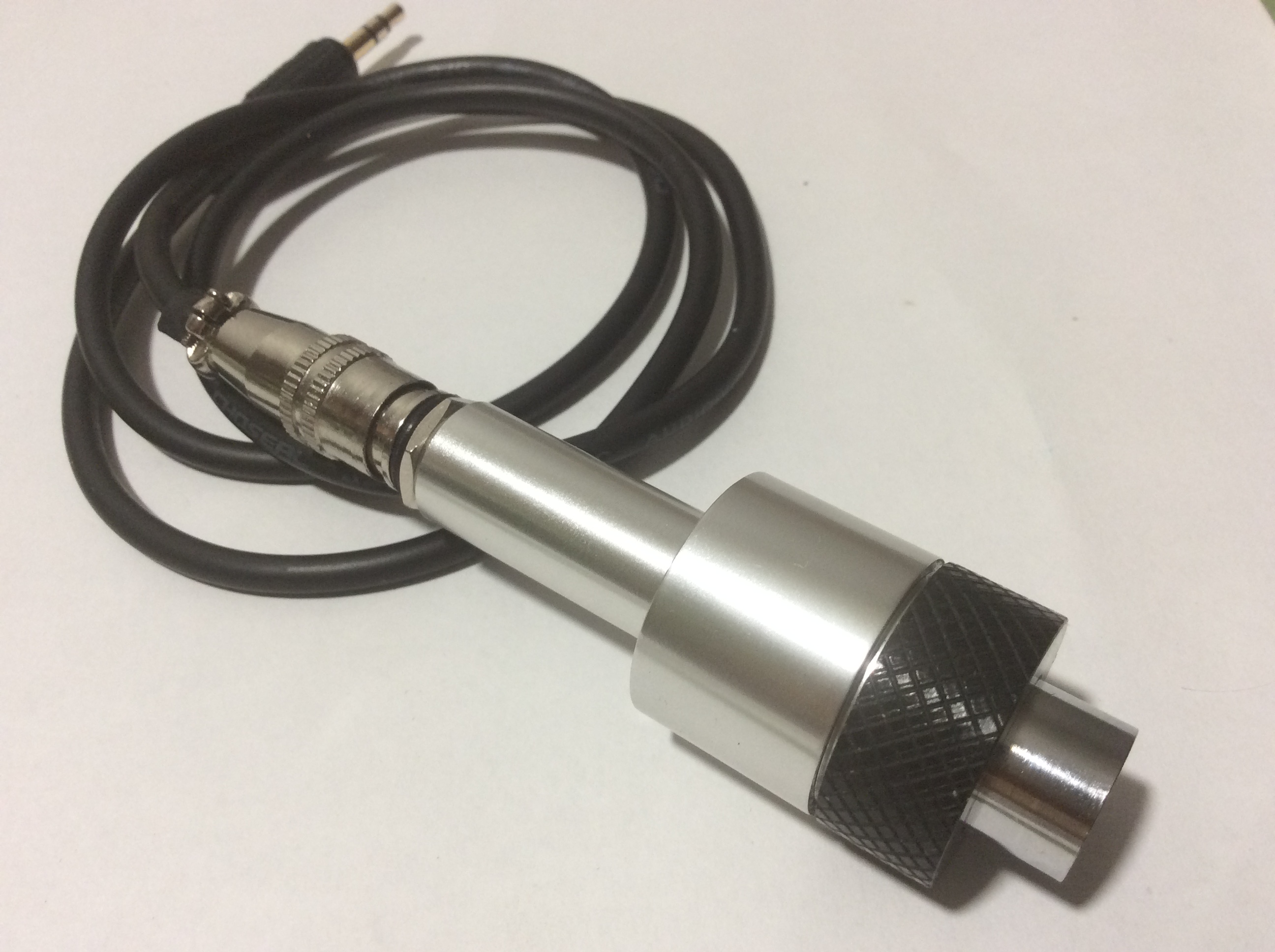
5- iMM-6 + 711 couplers.
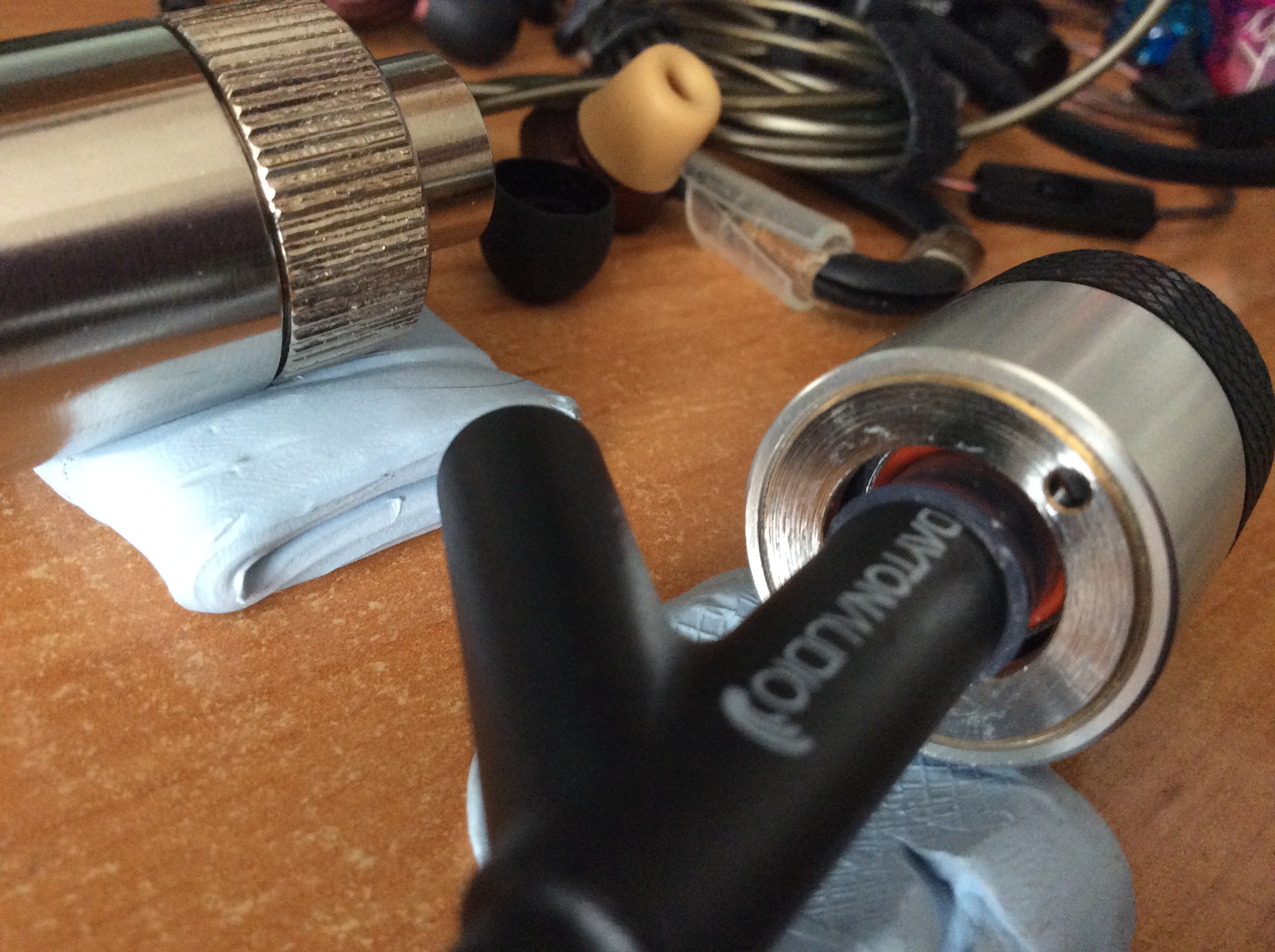
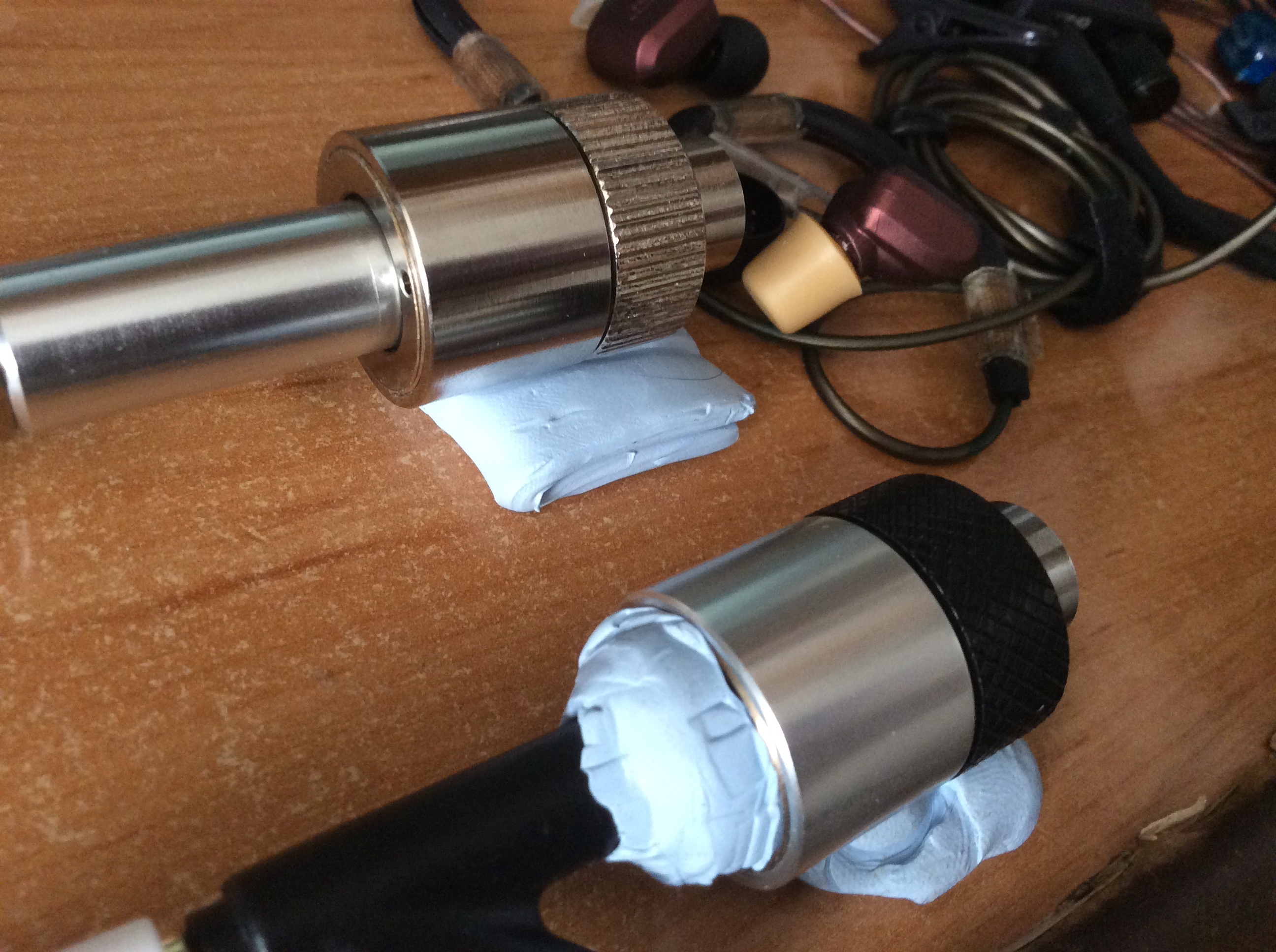
to fit the iMM-6 (6mm mic) into the couplers (12mm threaded), used a thick silicone o-ring and bluetac.
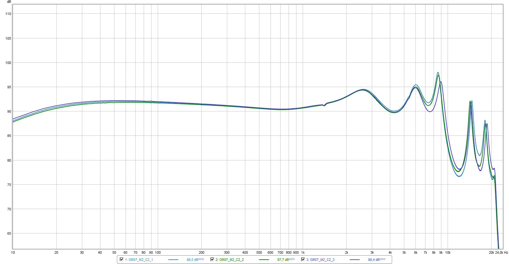
and here are the compare graphs of GR07 classic ed, using both 711 couplers, iMM-6 and the cheap mic.
C1 is the aluminum coupler; C2 is the stainless steel one.
M1 is iMM-6; M2 is the cheap mic which came with the alu coupler.
C1 + iMM-6 (different tips and insertion depth):
C2 + cheapMic (different tips and insertion depth):
C1 vs C2, + cheapMic (to compare couplers):
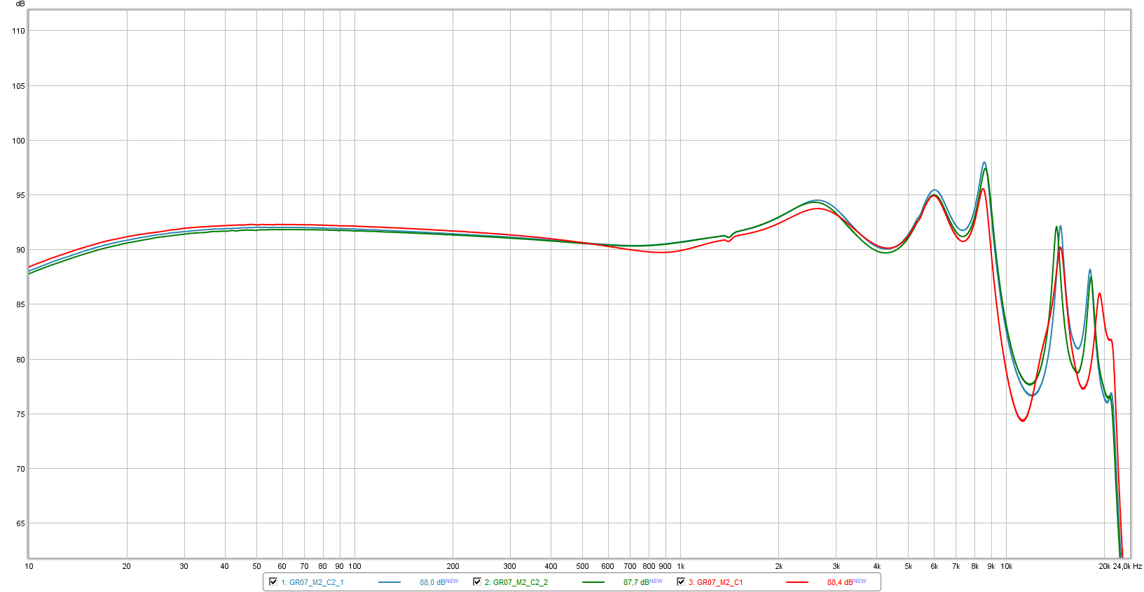
slight amplitude differences at the 8-9KHz peak and at the 11- 12KHz dip. maybe the o-ring I added into C2 to get extra isolation, did vary some distances (my bad, i should repeat the measurement without that o-ring); or that is the slight difference between couplers, I don't know. anyway, minimal difference.
C1, iMM-6 vs cheapMic (to compare mics):
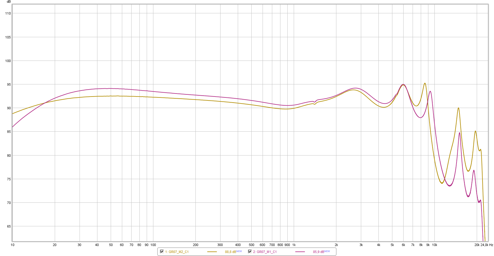
note the dip of the cheap mic in lows (40Hz centered), and its frequencies offset (from 9.5KHz to 8.5KHz); highs roll-off in iMM-6 (and some lows roll-off, but under 20Hz).
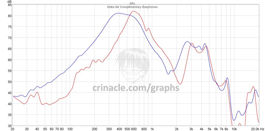
now, measuring Piston 3.
C1 + iMM-6 (different insertion depth):
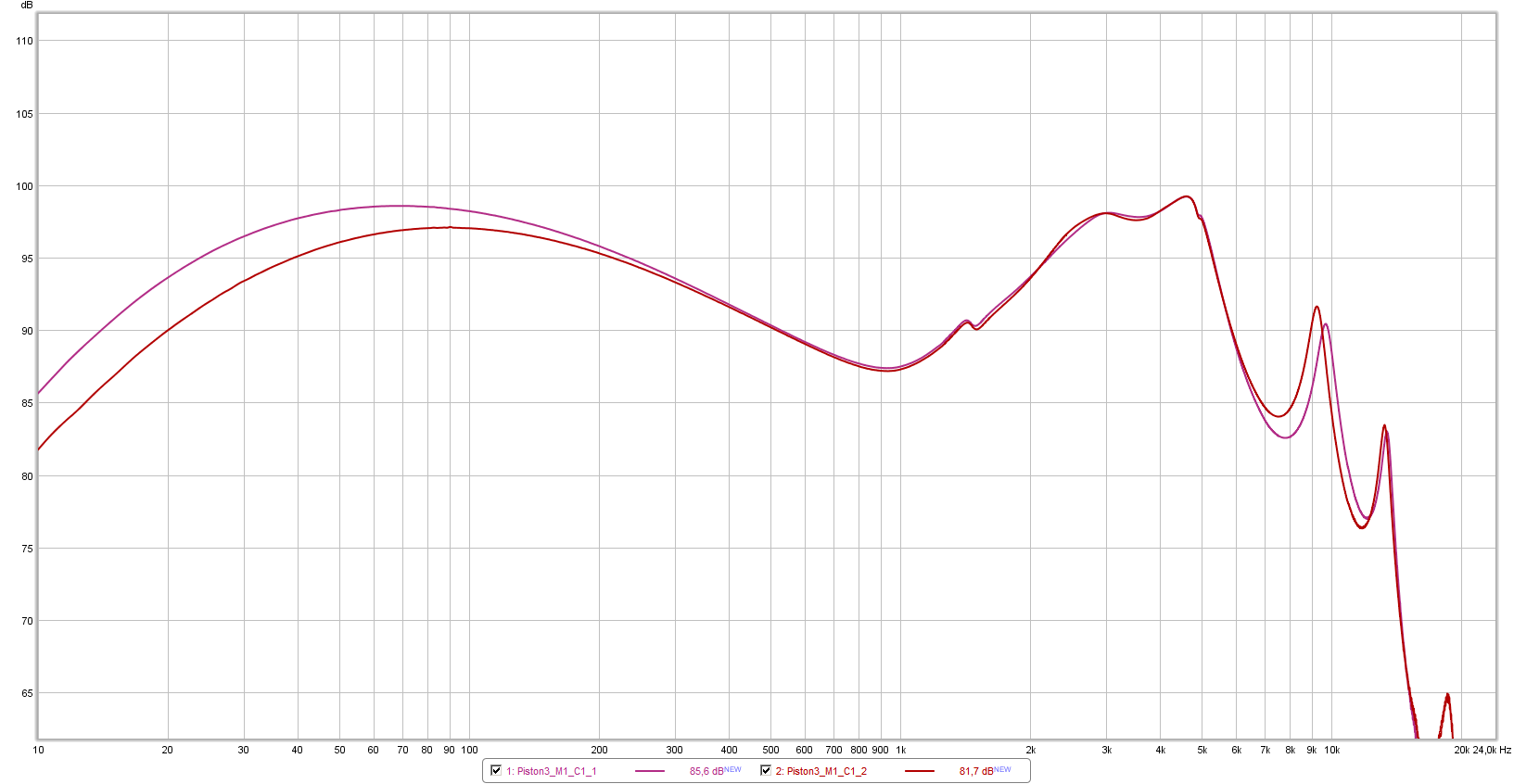
C1 + iMM-6 vs C2 + cheapMic
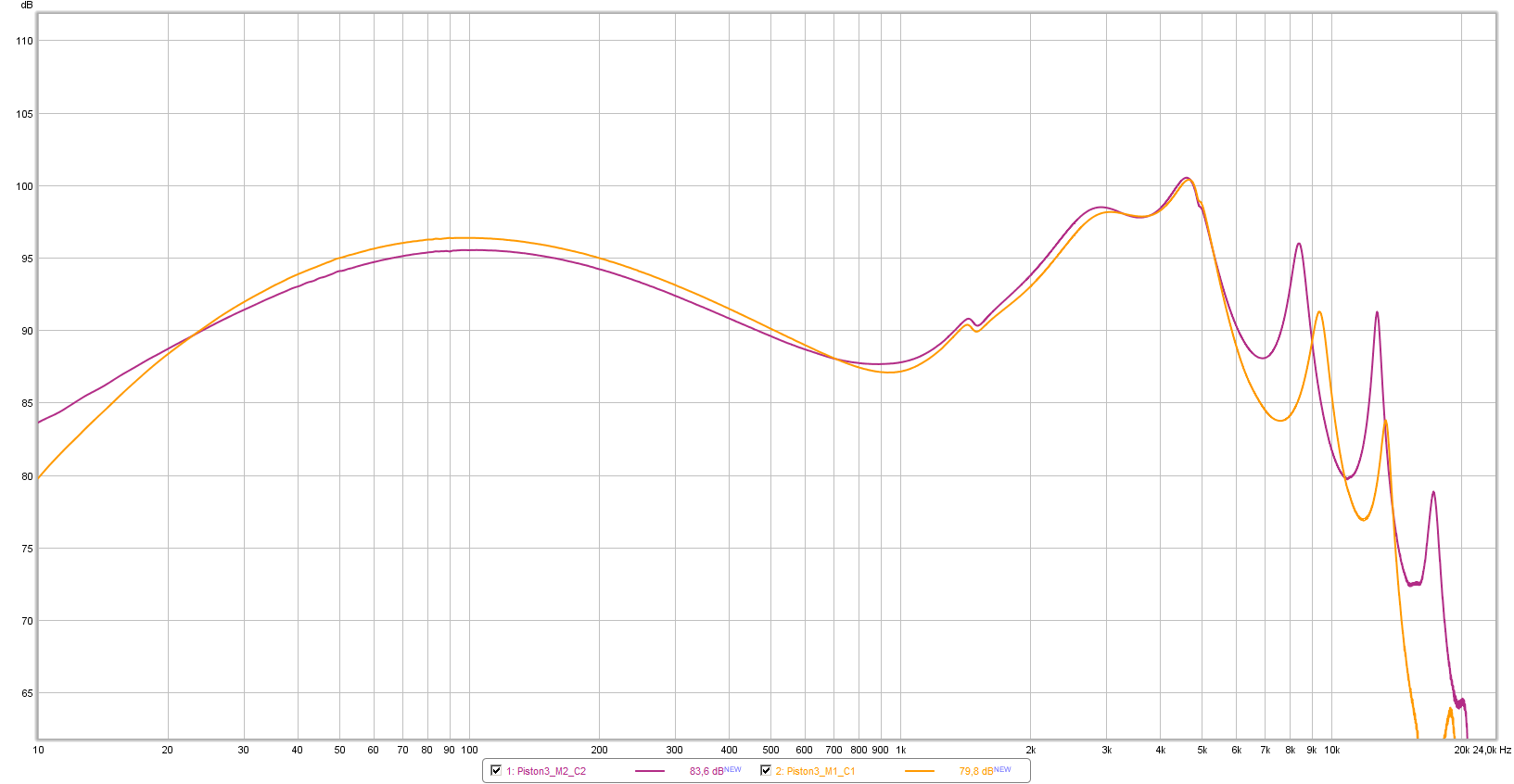
again similar differences, due to the mics, mainly. 9.5Khz -> 8.5KHz offset in the cheap one, and highs roll-off in iMM-6.
conclusions:
agreeing crinacle's comments, i think that an iec711 coupler helps to get closer to the real thing, and so does the mic.
having a iec711 coupler, i'd prefer using iMM-6 (easier to calibrate the highs roll-off) rather than the cheapMic (very difficult to fix that frequency offset).
but the insertion of iMM-6 into the coupler (using o-ring+bluetac) is not very stable, i guess. i'd probably cut the cillindrical threaded case of the cheap mic (about half size), insert iMM-6 into that case, adding some bluetac, and screw the result into the coupler.
i guess this rig, after some calibration (not so heavy), would satisfy my needs and expectations so far, and would be portable (laptop + dac + rig).
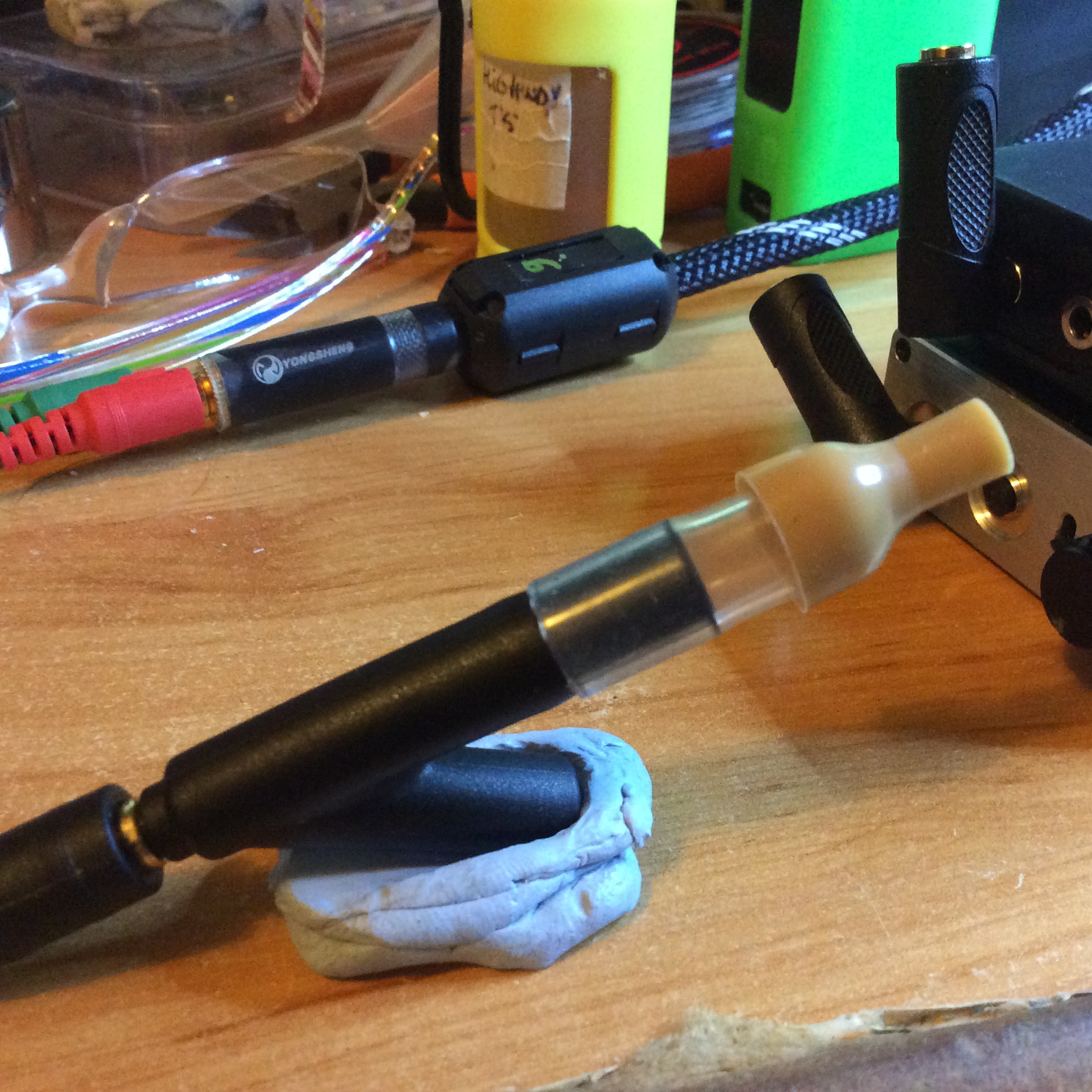
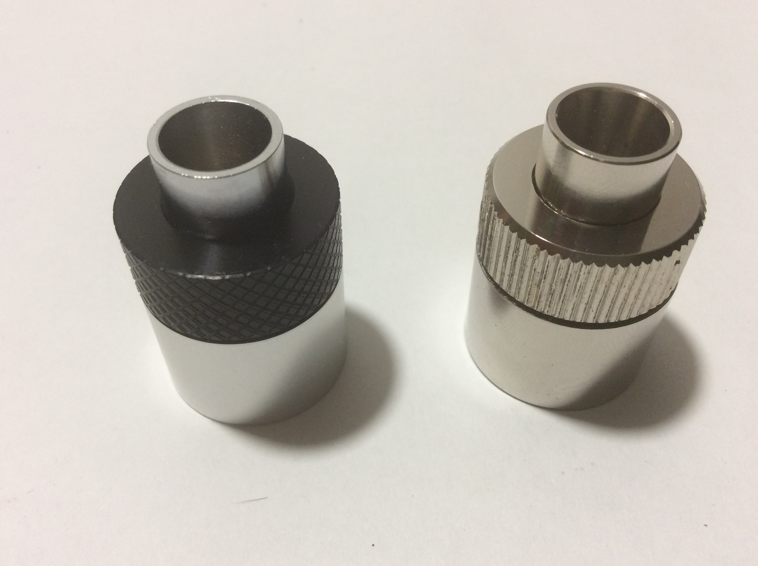
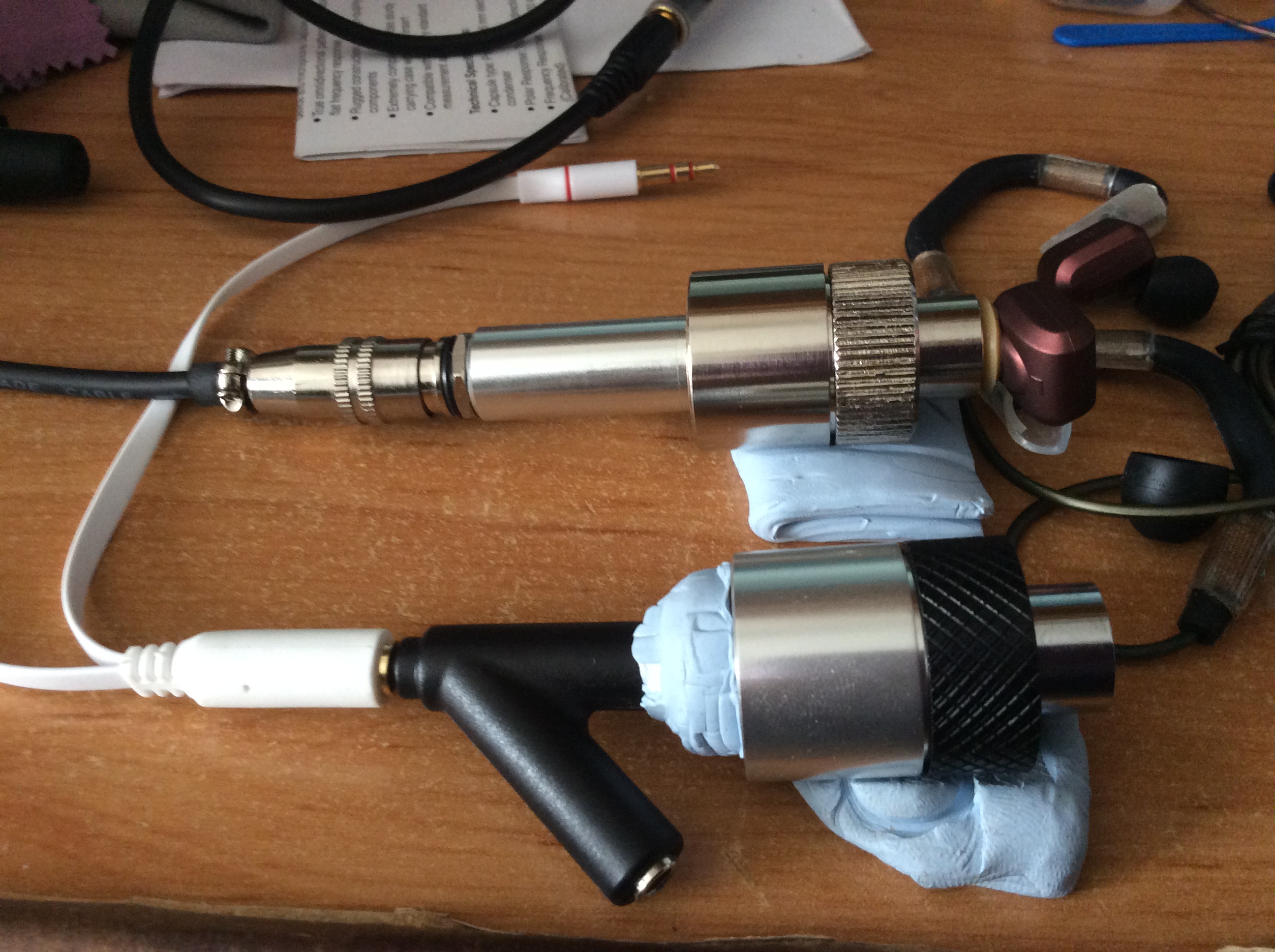
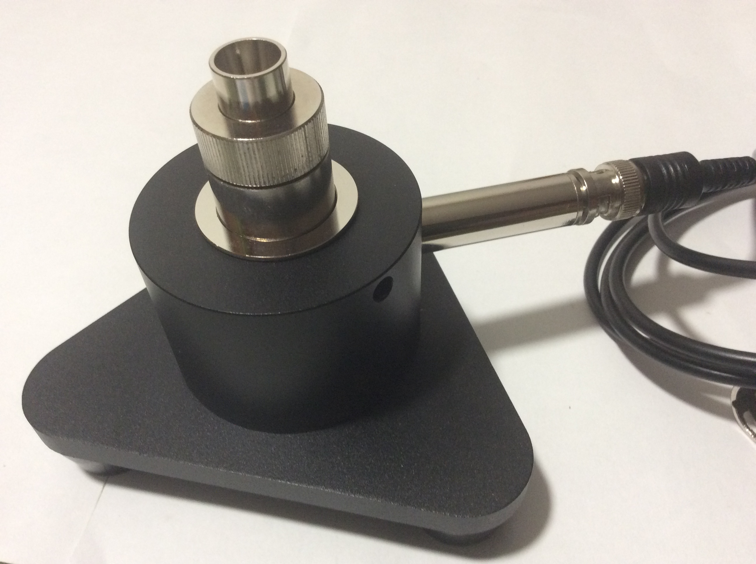
6- Chinese "pro" rig (iec711 coupler + precision mic + preamplifier + stand) + low noise and distortion input (E-MU 0404).
my PC soundcard inputs has excessive noise and distortion to be used to measure other parameters different to frequency response. so i purchased a low noise and distortion one: E-MU 0404.
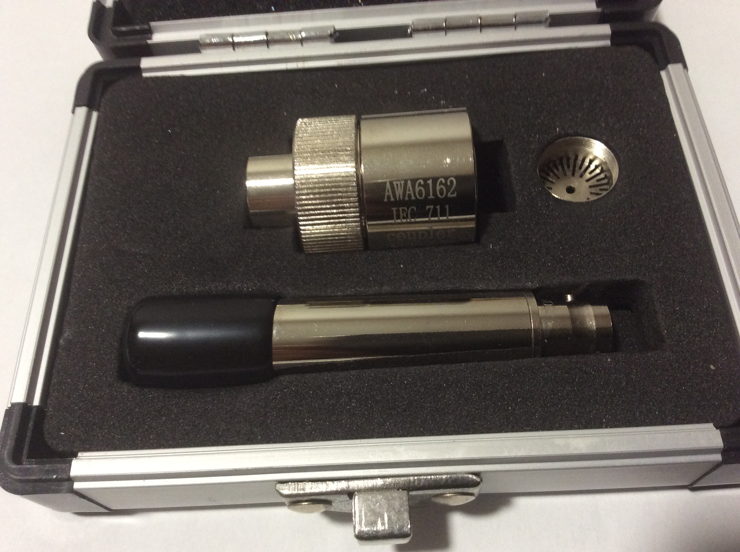
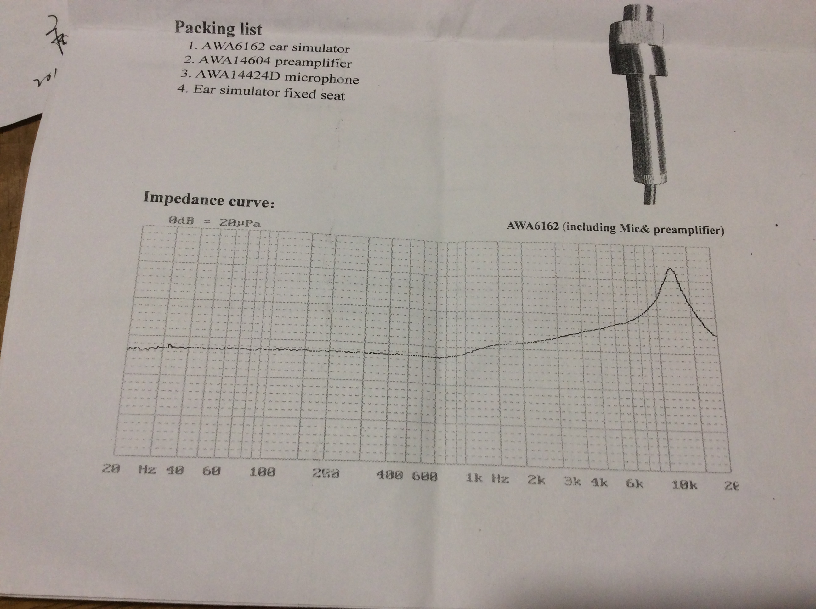
after spending in two iec711 couplers and this interface, thought i should try a "pro" calibrated mic. so purchased a chinese one, AWA14424D (calibration provided in a piece of paper, like GRAS ones), very very fragile.. which came mounted into a new iec711 coupler (AWA6162) to minimize the risk of damaging the mic while being mounted, and together with an appropriated preamplifier (AWA14604C) and an stand/base. Ouch, ouch, ouch, this did hurt my wallet badly.
now i have two spare iec711 couplers (if anyone is interested, pm me).
i've finished my other tasks, six months later, so i'll restart with audio again.
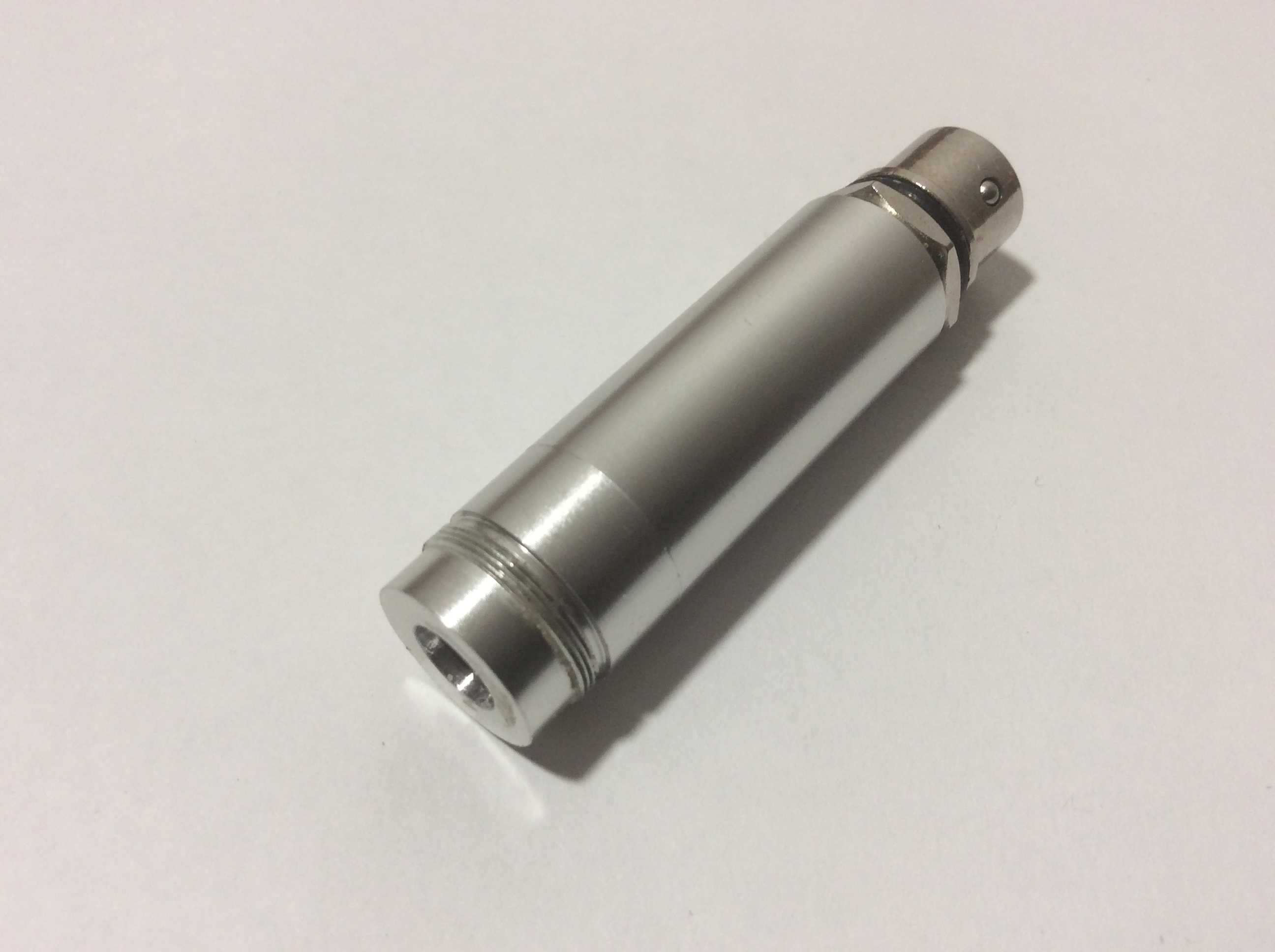
here are some pics of the new rig:
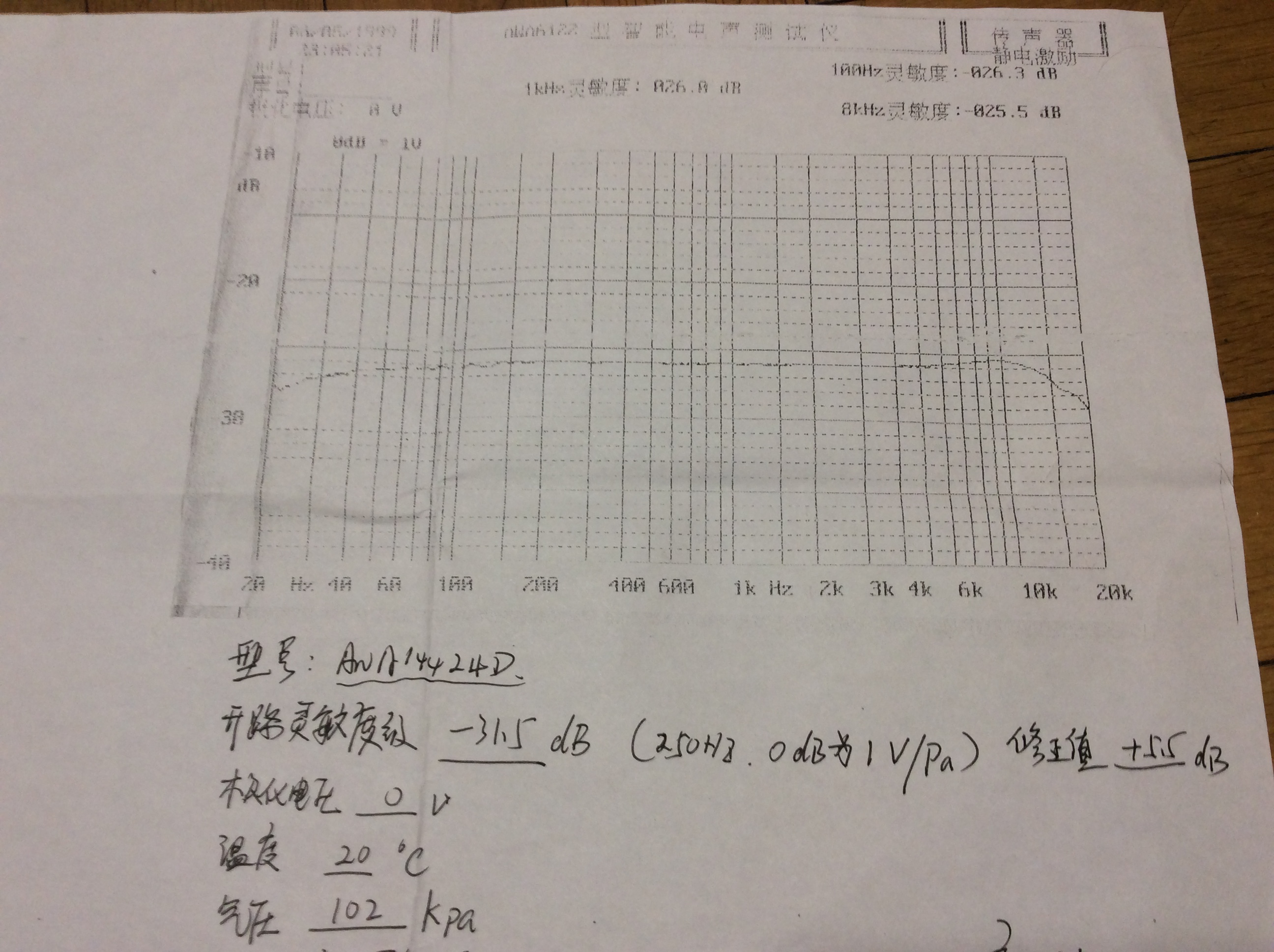
(another parameter, wrote in chinese -can't translate it-, says 76% at the end of the paper -wasn't caught by the cam-)

do you get significant variations in say THD+N or simply noise between the couplers? I'm itching for some slightly less lowfi measurement rig, like lowfi+(crazy, I know). so I'm really interested in the range of actually affordable gear for a little more than simple FR. but I wonder if money and efforts won't just be drowned under how bad everything else still is. or that I'm doing all this right next to my noisy laptop fans and the street.
*starts chanting the list of subjective biases*Wetware collates like nothing else. Procedure and associated kit can muck that up. Many work tirelessly to not hear differences and succeed.

 i don't know which is the right measurement (and probably i'll never know). by the moment, i'm using measurements from people which are using expensive pro gear, as a reference.
") ) to show the response curve of just the electronics. Anyone with an idea why all the mics give such different results, especially in the bottom end are most welcome to comment!
) to show the response curve of just the electronics. Anyone with an idea why all the mics give such different results, especially in the bottom end are most welcome to comment!


