


joneeboi
Headphoneus Supremus
- Joined
- Jul 7, 2006
- Posts
- 1,919
- Likes
- 20
Greetings DIY subforum,
I am interested in designing a USB-powered headphone amplifier that fits with tooleAudio's BantamDAC in a Hammond Mfg. 1455C80x case. I have had this idea in my head for maybe a year, but flying solo, I haven't been able to get very far. My interest was tickled by rds' USB Powered Pimeta thread which brought up the topic of powering an amplifier with USB power. I got the brilliant idea to design a USB-powered headphone amplifier when my Toshiba laptop's physical volume knob was snapped off and music was impossible to get from the onboard sound card. I figured I'd make an Alien DAC and throw it into a 1455C80x with a USB-powered amplifier before interest waned when I got a new laptop and I got music again. However, thinking about it again has made me really want to do this anyway. I figured I should contribute my time and energy to this board for all I've gained from it, and I want to do it for fun as well.

First things first, how viable is a USB-powered headphone amplifier? Basically, I want to recreate my own version of the dsavitsk's HPDAC but with just the amplifier section. Maybe I'd be better off including my own DAC section, but there's a perfectly good module I can point to without spending time and energy unnecessarily.
Next, I outline my design goals in order of highest priority to lowest.
I realize I'm walking alongside giants in this forum, so I'm open to learning from all of you. To be honest, it's a bit intimidating even starting this thread which is partly why I didn't start one for so long. I'm completely open to doing the legwork necessary for getting this idea out the door, I just need ideas first.
Now, let's talk specifics.
The biggest hurdle here, I feel, is power supply. rds wanted to power his PIMETA, but there is the tricky issue of the virtual ground versus "true earth" ground. This device will be lugged around with my laptop, so the earth ground will be whatever the laptop uses.
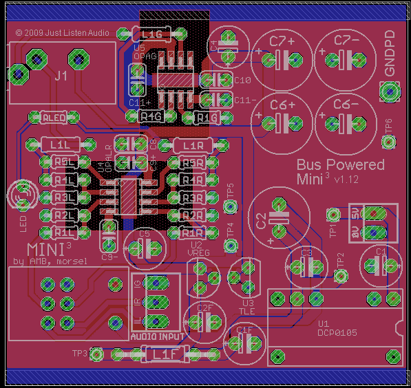
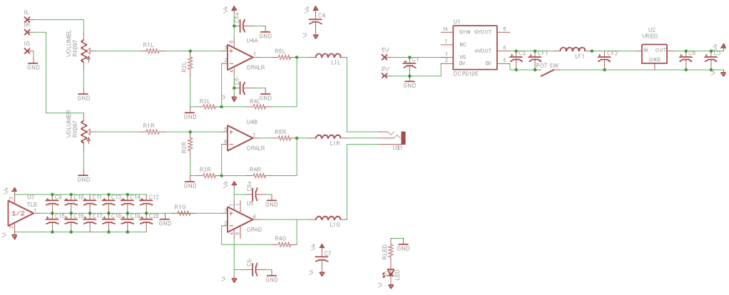
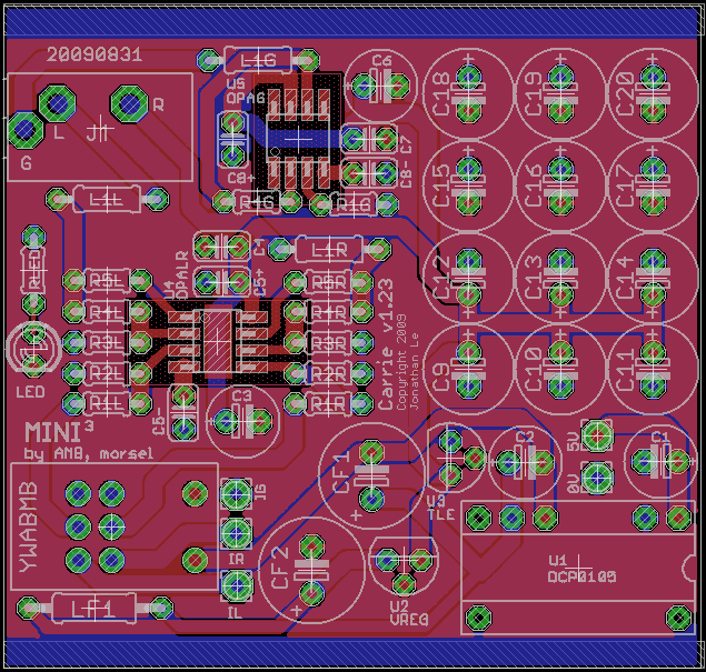
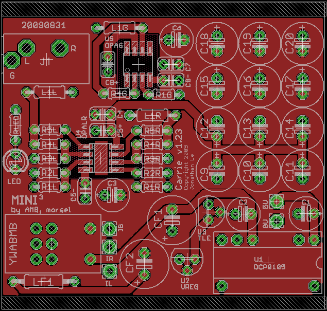
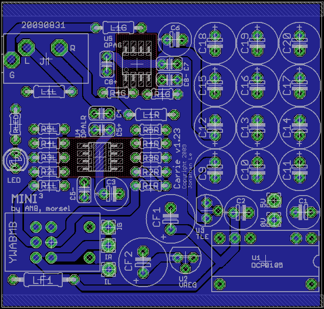
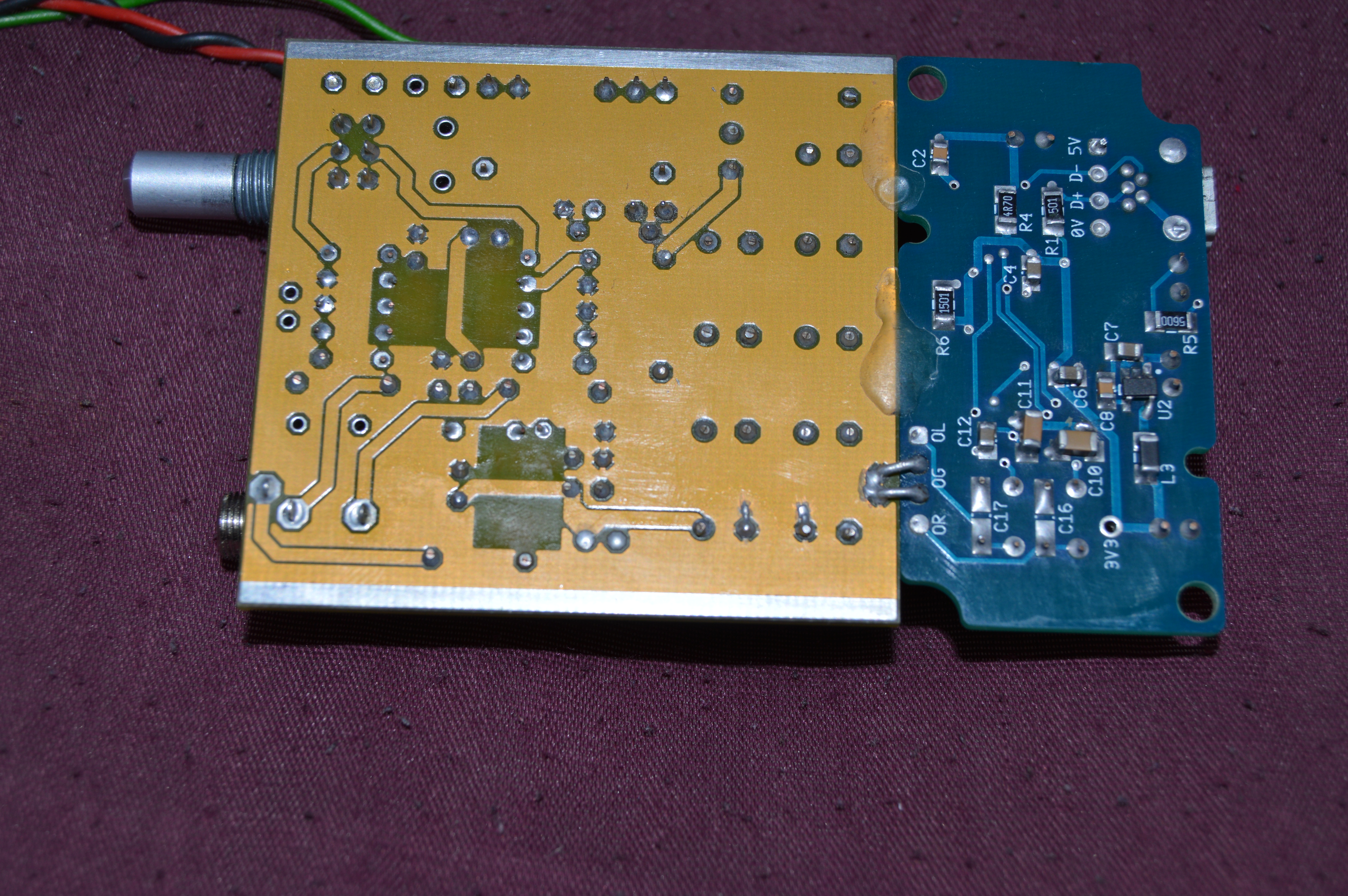
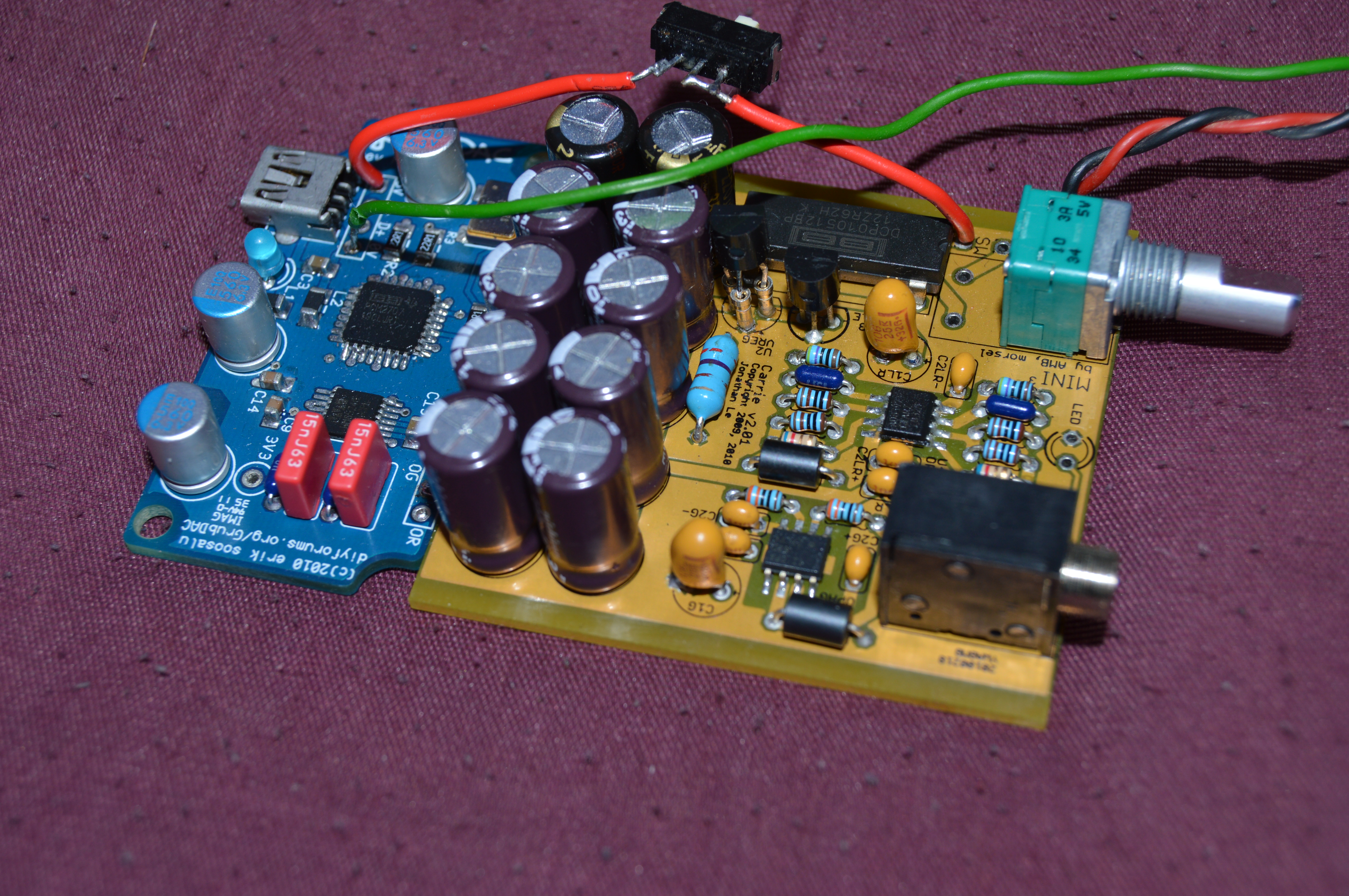
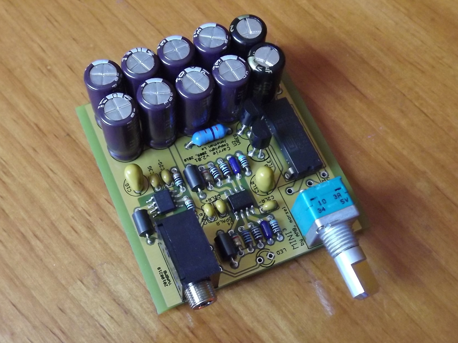
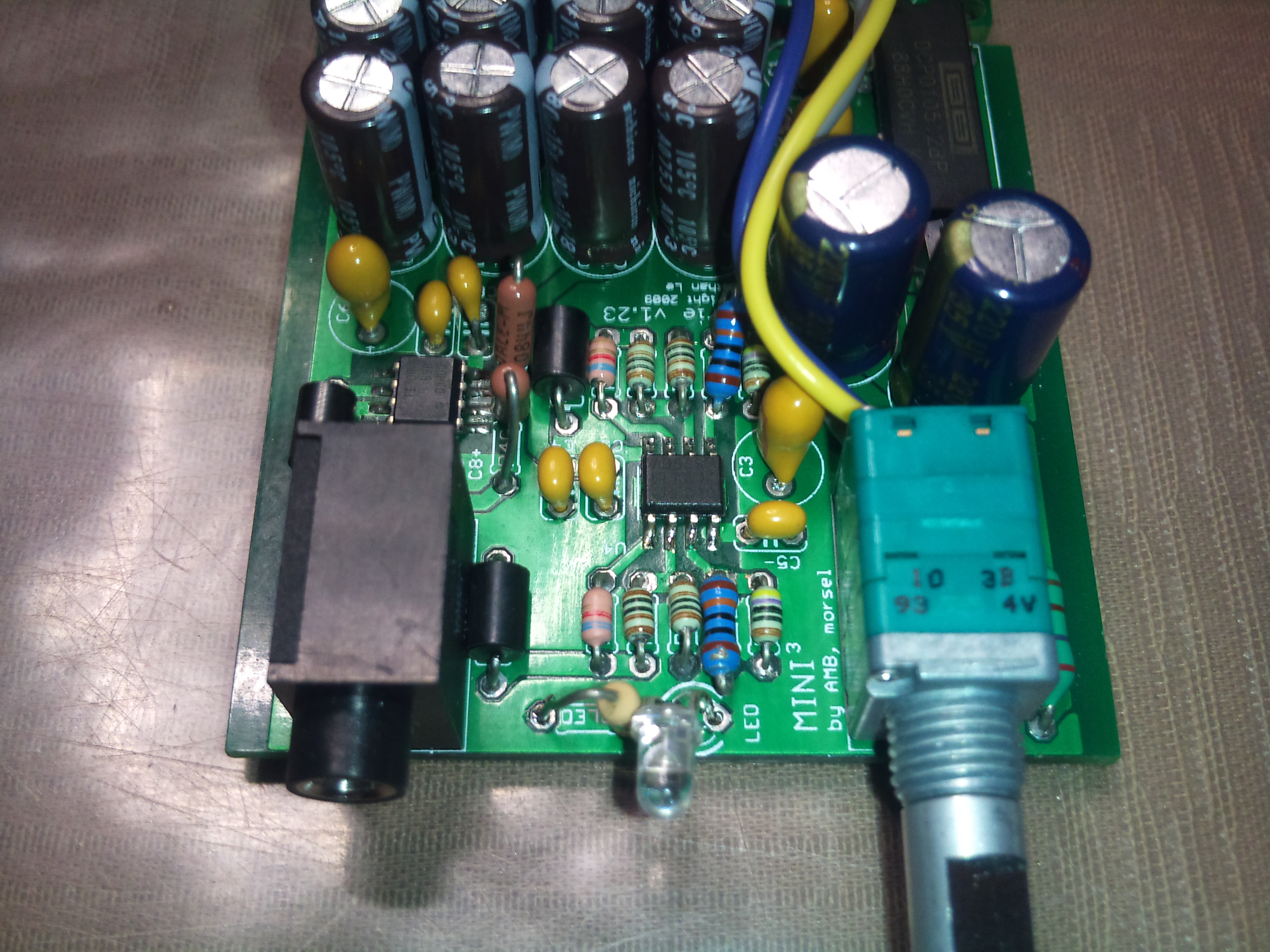
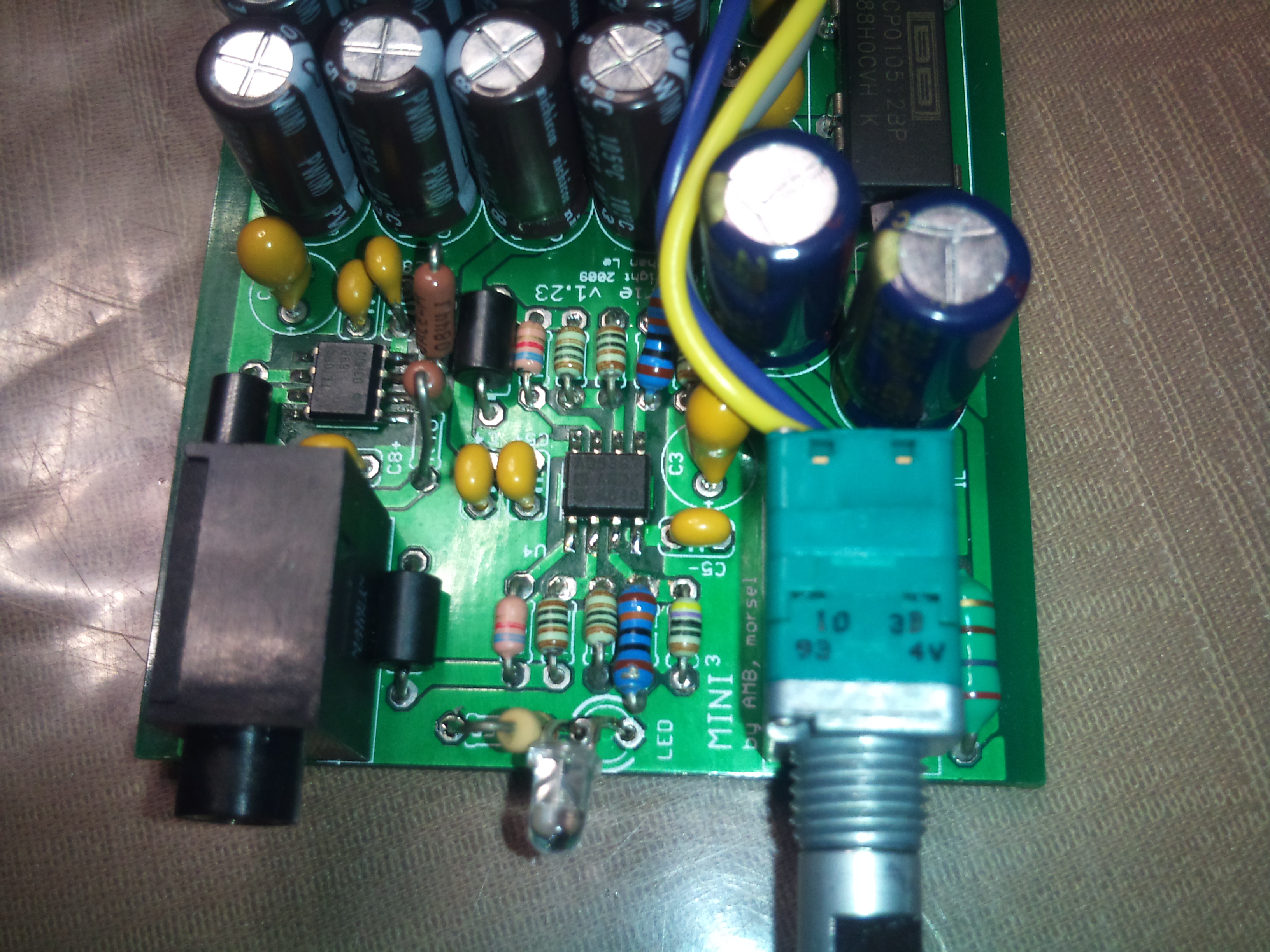
I was thinking of going with a 3-channel CMoy design. Most DIY SS amps I've seen run this course while using virtual ground, eg. PIMETA, PPAv2, M^3, Mini^3, so it won't be as easy as lifting the amplifier schematic from one of those designs and plugging it into a DC-DC boosting circuit. Buffers probably won't be implemented because of the already heavily loaded power supply. If there is room left over, maybe I'll consider it. Keep in mind that the BantamDAC will also be connected to the USB port, so the PCM2702 and TPS regulators will be drawing some current as well. I hope to have a circuit that circumvents the whole trouble of virtual ground vs. earth ground.
I'm not tied to any one set of opamps at the moment. I don't have much experience outside of OPA627, OPA2134, OPA2132, OPA2227, OPA2107, AD8320, AD8310, JRC4556, AD8397 and OPA690. Think CMoy, PIMETA, A47 and Mini^3. Any suggestions? Opamp rolling sounds tempting, but I'm worried the DIP package will take too much board space. Also, sticking to a certain set of opamps will help with containing current draw, but maybe that can be decided by the builder.
So that's about it for now. I really should be studying for finals at the moment, but that can wait just a bit. I'll be done all my semester on the 17th, but beyond then, I'll have plenty of time to work on it even into the new year as I am out on an eight month Engineering co-op work term. Any and all comments are welcome. I apologize in advance to those who are tired of seeing yet another one of joneeboi's threads with super huge first posts.
 I foresee oodles and oodles more of me updating the original post.
I am interested in designing a USB-powered headphone amplifier that fits with tooleAudio's BantamDAC in a Hammond Mfg. 1455C80x case. I have had this idea in my head for maybe a year, but flying solo, I haven't been able to get very far. My interest was tickled by rds' USB Powered Pimeta thread which brought up the topic of powering an amplifier with USB power. I got the brilliant idea to design a USB-powered headphone amplifier when my Toshiba laptop's physical volume knob was snapped off and music was impossible to get from the onboard sound card. I figured I'd make an Alien DAC and throw it into a 1455C80x with a USB-powered amplifier before interest waned when I got a new laptop and I got music again. However, thinking about it again has made me really want to do this anyway. I figured I should contribute my time and energy to this board for all I've gained from it, and I want to do it for fun as well.
First things first, how viable is a USB-powered headphone amplifier? Basically, I want to recreate my own version of the dsavitsk's HPDAC but with just the amplifier section. Maybe I'd be better off including my own DAC section, but there's a perfectly good module I can point to without spending time and energy unnecessarily.
Next, I outline my design goals in order of highest priority to lowest.
- USB-powered
- Fit into the Hammond 1455C80x
- 3-channel CMoy amplifier
- Low-cost
- Relatively easy to build
I realize I'm walking alongside giants in this forum, so I'm open to learning from all of you. To be honest, it's a bit intimidating even starting this thread which is partly why I didn't start one for so long. I'm completely open to doing the legwork necessary for getting this idea out the door, I just need ideas first.
Now, let's talk specifics.
The biggest hurdle here, I feel, is power supply. rds wanted to power his PIMETA, but there is the tricky issue of the virtual ground versus "true earth" ground. This device will be lugged around with my laptop, so the earth ground will be whatever the laptop uses.
I was thinking of going with a 3-channel CMoy design. Most DIY SS amps I've seen run this course while using virtual ground, eg. PIMETA, PPAv2, M^3, Mini^3, so it won't be as easy as lifting the amplifier schematic from one of those designs and plugging it into a DC-DC boosting circuit. Buffers probably won't be implemented because of the already heavily loaded power supply. If there is room left over, maybe I'll consider it. Keep in mind that the BantamDAC will also be connected to the USB port, so the PCM2702 and TPS regulators will be drawing some current as well. I hope to have a circuit that circumvents the whole trouble of virtual ground vs. earth ground.
I'm not tied to any one set of opamps at the moment. I don't have much experience outside of OPA627, OPA2134, OPA2132, OPA2227, OPA2107, AD8320, AD8310, JRC4556, AD8397 and OPA690. Think CMoy, PIMETA, A47 and Mini^3. Any suggestions? Opamp rolling sounds tempting, but I'm worried the DIP package will take too much board space. Also, sticking to a certain set of opamps will help with containing current draw, but maybe that can be decided by the builder.
So that's about it for now. I really should be studying for finals at the moment, but that can wait just a bit. I'll be done all my semester on the 17th, but beyond then, I'll have plenty of time to work on it even into the new year as I am out on an eight month Engineering co-op work term. Any and all comments are welcome. I apologize in advance to those who are tired of seeing yet another one of joneeboi's threads with super huge first posts.