


I thought the DSP was soldered on the DAC board on the Master-7 (which was the main difference vs. the old Ref-7.32)?
You are using an out of date browser. It may not display this or other websites correctly.
You should upgrade or use an alternative browser.
You should upgrade or use an alternative browser.
Audio-Gd Master 7 - Discrete Fully Balanced DAC (PCM1704)
- Thread starter DarknightDK
- Start date
aive
100+ Head-Fier
- Joined
- Feb 20, 2013
- Posts
- 247
- Likes
- 21
I thought the DSP was soldered on the DAC board on the Master-7 (which was the main difference vs. the old Ref-7.32)?
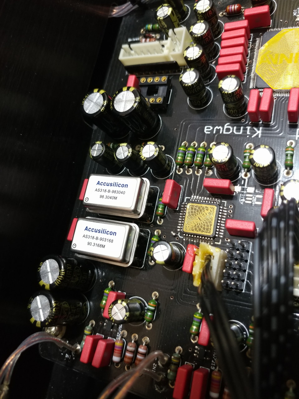
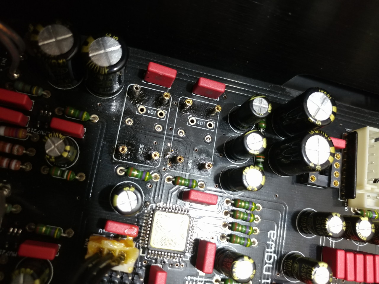
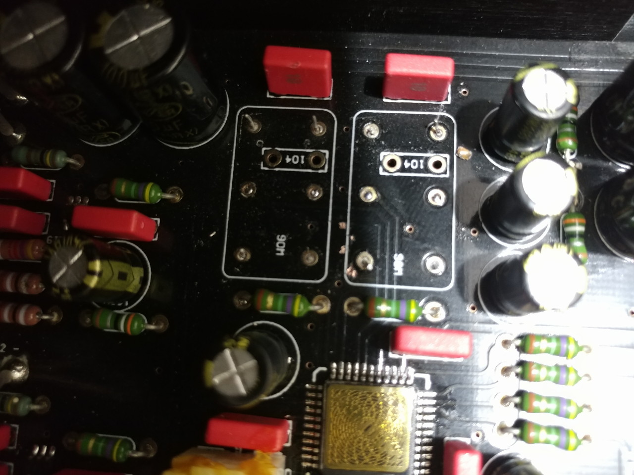
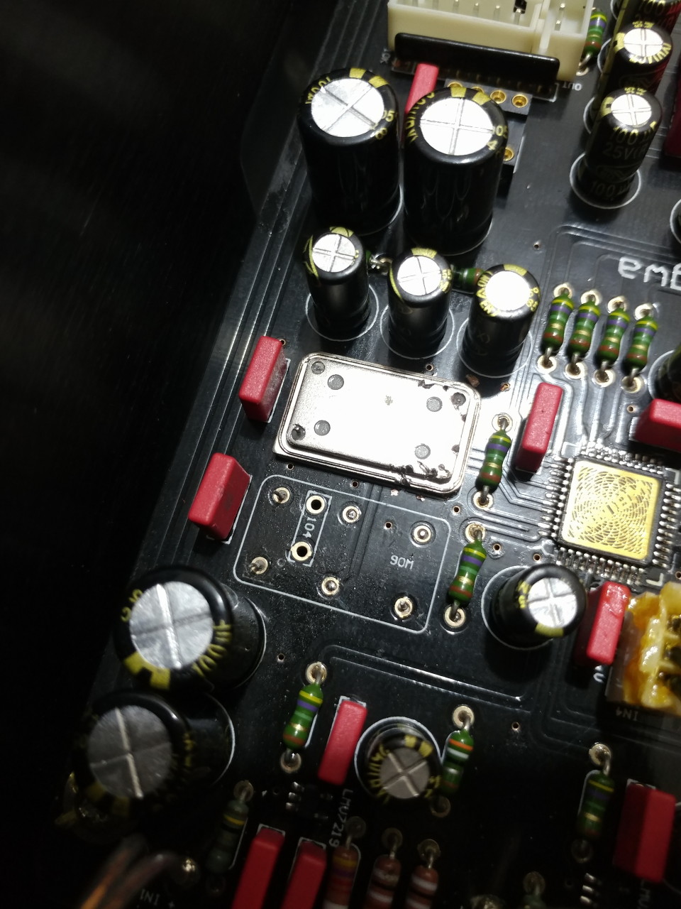
Unsure what you mean. M7 has 3 boards - two output DAC boards one for each channel and a DSP board in the centre compartment. I completely removed the DSP board and replaced it with the Ian NOS FIFO solution that feeds PCM straight into the DAC boards for analogue conversion and output amplification.
motberg
500+ Head-Fier
Me too. Using the DI 2014 interface bypasses the usb port. But how to bypass the DSP is still obscure to me.
Maybe simply taking off the appropriate jumper?
or is this FIFO board meant to remplace the DSP?
Hi,
Are you using the HDMI i2S from the DI2014 to the M7? That is probably the best option with a quality HDMI cord as short as possible, 0.3M if you can make it, and not longer than 1M using a higher quality cable.
To get a taste of the effects of limiting the DSP, power off the DAC and all attached devices, remove the top (I think it is 4 pcs. of 3mm allen head screws and 4 small phillips head screws).
Picture of the inside here: http://www.audio-gd.com/Master/Master-7/M7EN_Use.htm
And add 3 jumpers as per below:
BYPASS (JUMPER ON) factory
DITH (JUMPER OFF)
IPS1 (JUMPER OFF)
ATT0 (JUMPER ON) add
ATT1 (JUMPER ON) add
IPS0 (JUMPER ON) add
PLLEN (JUMPER OFF)
Do not remove the BYPASS jumper stock from the factory. There are a lot of posts in this thread with various ideas, but I am pretty sure this is the setting recommended by Audio GD. (Kingwa just commented about this at the Audio-GD Chinese BBS)
To more bypass the DSP, you can jumper the IPS1, but that will probably run into trouble with phase as aive mentions... so do not jumper IPS1.
I have researched this a lot before jumping in (sorry I waited so long...), and using these settings the results are amazing.
Similar to your DI2014, I am using a Tanly DDC with HDMI i2S (1M Wireworld Starlight 6) to the M7.
If you want to test quickly if your phase is OK, find a 16/44 test track such as the Stereophile one which will have sounds from each speaker, then centered, and also out of phase.
Note the out of phase condition may not show up on high resolution tracks, so you need test with standard CD resolution, but my guess is with the DI2014, and good HDMI short cable, you should be OK.
A few pages back I made some links to the FIFO boards info in other forums - but honestly, I suggest to just jumper as per above to check, and if you like the results, then wait a little to see what Kingwa has dreamed up with his new NOS options.
DACLadder
Headphoneus Supremus
- Joined
- Feb 16, 2013
- Posts
- 2,280
- Likes
- 2,109
I thought the DSP was soldered on the DAC board on the Master-7 (which was the main difference vs. the old Ref-7.32)?
The M7 DSP board output feeds I2S to the left and right DAC boards. In photos of the M7 gut shot you can see the wires (silver colored - four each side) in about the middle of the DSP board fed through the internal wall dividers to either side. I believe "aive "unsoldered these DSP board I2S feeds to isolate and then used Ian's FiFo board to drive the DAC boards directly by its I2S signals. At least this is how I understand how he did it.
Oh wow, I thought the DACs were on the middle board. I never paid close attention to it before. Thanks for the head's up!
I was confused because the DSP board actually used to be (Ref 7) detachable from the receiver board and the main improvement in the Master-7 is that it is soldered directly on the board now.
So the middle board is only the receiver + DSP, interesting. Much easier to take out and integrate a new receiver indeed. The S/PDIF inputs suck anyway...
I hope Kingwa will release the new FIFO + asynchronous clocking to the normal Master-7 (not just the NOS version). Better yet, offer all 3 configurations (NOS1 / NOS2 / OS) in one package and allow the user to select it in the menu
 .
.
I was confused because the DSP board actually used to be (Ref 7) detachable from the receiver board and the main improvement in the Master-7 is that it is soldered directly on the board now.
So the middle board is only the receiver + DSP, interesting. Much easier to take out and integrate a new receiver indeed. The S/PDIF inputs suck anyway...
I hope Kingwa will release the new FIFO + asynchronous clocking to the normal Master-7 (not just the NOS version). Better yet, offer all 3 configurations (NOS1 / NOS2 / OS) in one package and allow the user to select it in the menu
aive
100+ Head-Fier
- Joined
- Feb 20, 2013
- Posts
- 247
- Likes
- 21
The DAC boards are fed PCM signals which feed straight into the 1704 chips - all I2S conversion and manipulation is done on the DSP.
So I just unsoldered the connections to the DAC boards and tapped in with my own PCM source (Ian makes an I2S to PCM board to go with his FIFO).
So I just unsoldered the connections to the DAC boards and tapped in with my own PCM source (Ian makes an I2S to PCM board to go with his FIFO).
DACLadder
Headphoneus Supremus
- Joined
- Feb 16, 2013
- Posts
- 2,280
- Likes
- 2,109
The DAC boards are fed PCM signals which feed straight into the 1704 chips - all I2S conversion and manipulation is done on the DSP.
So I just unsoldered the connections to the DAC boards and tapped in with my own PCM source (Ian makes an I2S to PCM board to go with his FIFO).
Thanks for the clarification!
Are the Left and Right PCM source identical (meaning both L&R channels are sent to the DAC+Analog boards)?
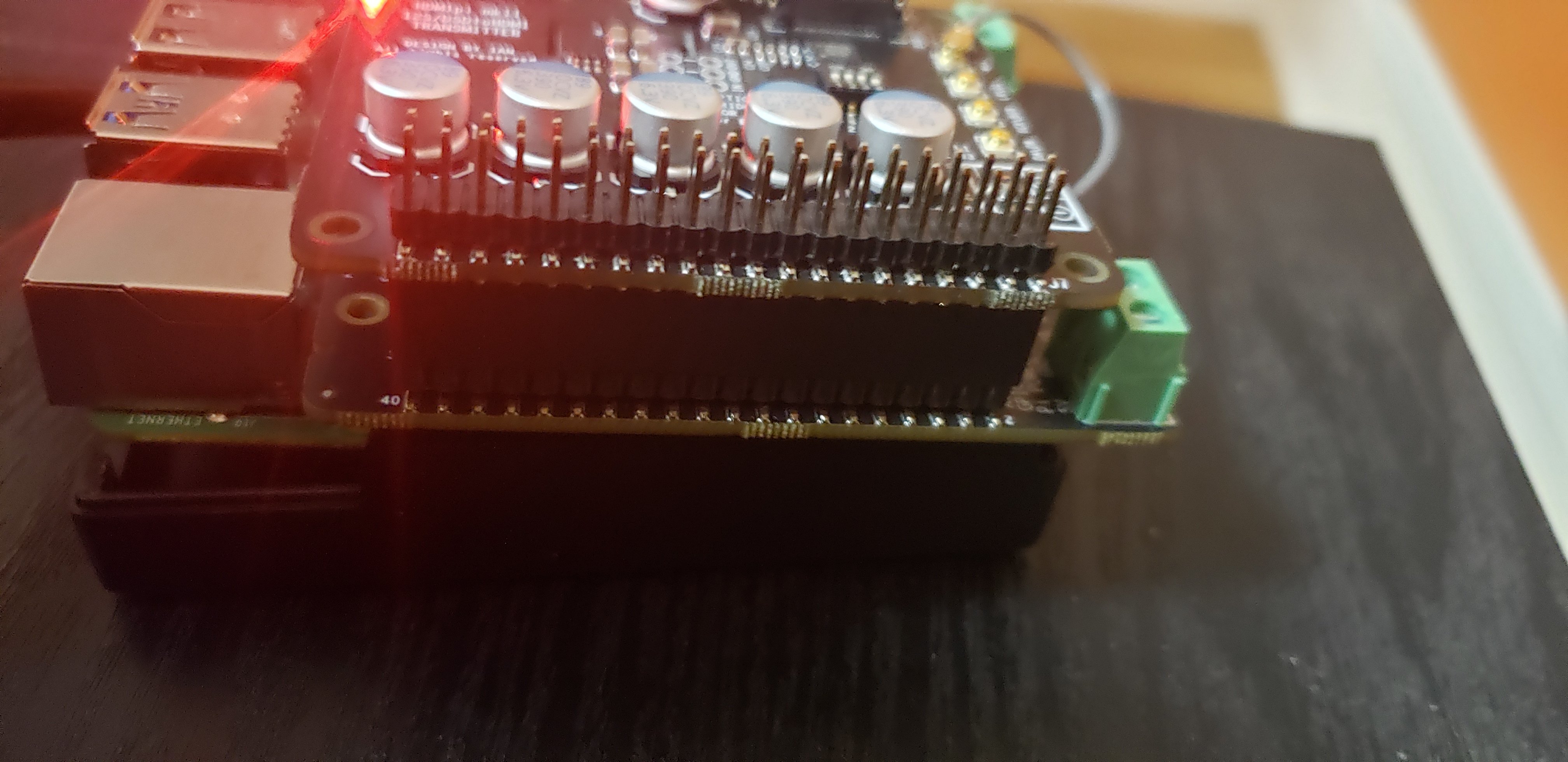
I could see a raspberry Pi + DAC+pro tapped to it for a neat streamer DAC. There should be room for an extra PSU, once the DSP board is removed.
I could see a raspberry Pi + DAC+pro tapped to it for a neat streamer DAC. There should be room for an extra PSU, once the DSP board is removed.
aive
100+ Head-Fier
- Joined
- Feb 20, 2013
- Posts
- 247
- Likes
- 21
Are the Left and Right PCM source identical (meaning both L&R channels are sent to the DAC+Analog boards)?
I could see a raspberry Pi + DAC+pro tapped to it for a neat streamer DAC. There should be room for an extra PSU, once the DSP board is removed.
Nope - channel specific data to each DAC board. I.e. only left data and clocks goes to left DAC board.
Plenty of room in centre for FIFO and RPi but you may struggle with power supplies for these components. Might be a photo of my setup on diyAudio - mines pretty bodgy

Benny-x
1000+ Head-Fier
Nope - channel specific data to each DAC board. I.e. only left data and clocks goes to left DAC board.
Plenty of room in centre for FIFO and RPi but you may struggle with power supplies for these components. Might be a photo of my setup on diyAudio - mines pretty bodgy
If you were willing to go that far putting an RPi INSIDE the M7 though, it wouldn't be hard to just unsolder one of the SPDIF connectors, then either attach a male DC connector which runs to a female to plug into the RPi and have a small LPS outside or just run a DC cable through the SPDIF hole into the RPi inside directly. I mean, if you're getting dirty like that then what difference does it make to just go a little further. The hole is already there and by going down the "Internal RPi Streamer" route you've clearly decided what interface you're going to be using with the DAC anyway.
That's interesting talk about the FIFO board working, somewhat easily. I see a lot of stuff on DIY Audio and wherever, but I find the application of the components tend to need a lot of work. This FIFO board sounds neat and like a nice answer to the "good I2s" question that's always going on.
motberg
500+ Head-Fier
I am just starting to learn about this but can't the RPi send i2S to the Ian FIFO directly? You would not need the SPDIF conversion...
- Joined
- Apr 11, 2006
- Posts
- 1,036
- Likes
- 160
I am just starting to learn about this but can't the RPi send i2S to the Ian FIFO directly? You would not need the SPDIF conversion...
Hello Tom,
I had to correct something: Ian is assembling those FIFO II boards completely, so no sweat

RPI can send I2S directly to Ian's FIFO II, but, you need an Isolator board after the FIFO II board, AND a dual clock board after the isolatorboard.
RPI has NO masterclock.
Tini
New Head-Fier
- Joined
- Dec 21, 2010
- Posts
- 30
- Likes
- 10
Hi guys,
I have a M7 with an I2S RJ45 connection but I use the Amanero USB and it sounds very good after a lot of tweaking with my computer.
I was thinking if it's possible to use the I2S connection (in the M7, not the RJ45 connection) for real-time Ethernet streaming audio with the AVB-DGK from MiniDSP (https://www.minidsp.com/products/network-audio/avb-dgk).
But I need some help here. Can the AVB-DG module be build in the M7 and connected to the I2S and what would the SQ be from this?
Anyone thought about this or tried it already?
Regards,
Tini
DACLadder
Headphoneus Supremus
- Joined
- Feb 16, 2013
- Posts
- 2,280
- Likes
- 2,109
Hi guys,
I have a M7 with an I2S RJ45 connection but I use the Amanero USB and it sounds very good after a lot of tweaking with my computer.
I was thinking if it's possible to use the I2S connection (in the M7, not the RJ45 connection) for real-time Ethernet streaming audio with the AVB-DGK from MiniDSP (https://www.minidsp.com/products/network-audio/avb-dgk).
But I need some help here. Can the AVB-DG module be build in the M7 and connected to the I2S and what would the SQ be from this?
Anyone thought about this or tried it already?
Regards,
Tini
Interesting as the AVB-DG module may physically fit very well in the space where the AGD RJ45 board is located. Whether you can program the board to wake up and be in a state ready for use is another question and my require some work to accomplish.
As for sound quality the Master 7 responds well to low jitter clocks so if the board's clocks are good and I2S compatible then yes it can sound very good.
https://www.minidsp.com/images/documents/Product%20Brief%20-%20AVB-DG.pdf
Tini
New Head-Fier
- Joined
- Dec 21, 2010
- Posts
- 30
- Likes
- 10
In this manual you can read all about connecting it:
https://www.minidsp.com/images/documents/AVB-DGK%20Quick%20start%20guide.pdf
5V can be used from the M7 and it can be programmed but that's beyond my skills.
It seems very nice and it's not expencive. I use there microfone and I have the DSP2x4 and it's good stuff.
https://www.minidsp.com/images/documents/AVB-DGK%20Quick%20start%20guide.pdf
5V can be used from the M7 and it can be programmed but that's beyond my skills.
It seems very nice and it's not expencive. I use there microfone and I have the DSP2x4 and it's good stuff.
