


sajunky
Headphoneus Supremus
75Ohm was a standard for word clock in the professional audio equipment and TV installations.This is where I lose all my logic. Is this some sort of marketing 2 in 1 thing?
50Ohm was a standard in measuring equipment, amateur radio, military radar installations, etc.
When 10MHz clock was introduced, designers decided for 50Ohm cabling, I think it was in order to differentiate from the existing audio word clock systems. It makes sense, as these clock systems are functionally incompatible, i.e., word clock frequency depends on the current sampling rate, while 10MHz clock is fixed frequency and requires sophisticated clock synthesisers to work.
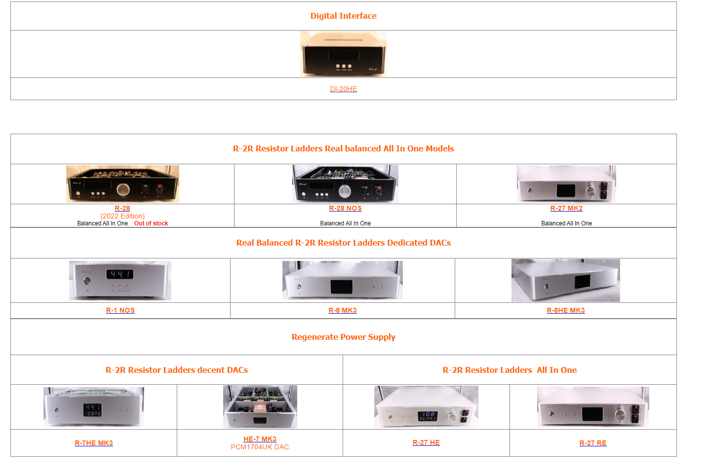
Audio GD has 75ohm output for a word clock, it is compatible with professional audio and 50Ohm inputs for 10MHz clock, it matches most of 10MHz sources. I don't see any deviation from a common practice.
A for compatibility of connectors, it depends. On the long cable runs impedance must be maintained to avoid standing wave (reflection on both ends: back and forward). However tolerance of cables impedance is not maintained very strict, making matching difficult, reflections on connectors are much smaller than cables. So matching connectors is less important. On the short runs matching impedance is even less important. It is why for the 10Mhz clock applications it can be assumed that these connectors are compatible.
Hope it clears any questions.
[EDIT] Similar discussion is pending in parallel. Can anyone repost this in high-end R-7 section? Someone has requested to cut my access there and - it was done.
Last edited:


