Almi's X-Fi Mod (Hotrodding Sound Blaster X-Fi models)
Jul 27, 2016 at 5:16 PM Post #121 of 154
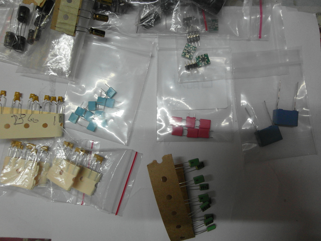
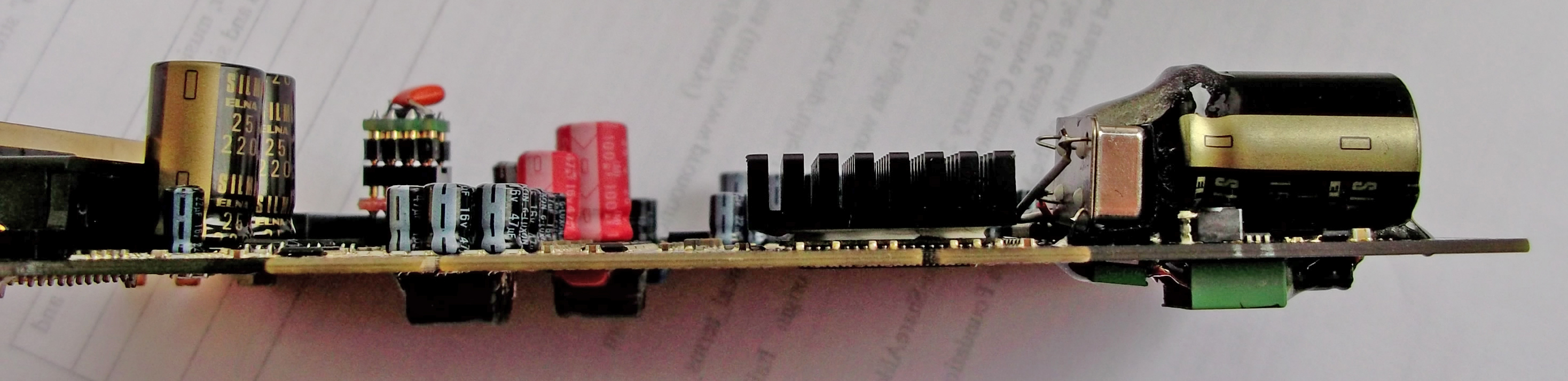
Not off topic because this tings are often universal. You can use the ceramic for the main filter cap or on the VDD of the DAC chip, but under 0.1uF is certainly small to experience the benefit. On other locations I suggest to use the films. My experiments not long ago on external DACs suggest the 0.1uF is only the minimum recommended to use. One thing what the circuits minimum need for the stable operation and another how they produce the best sound for the user. If let say you add 1, 2.2 or even 4.7uF film on the DAC's analog power supply cap, you get a clearer high and mid-range based on the capacitance. The 0.1uF only enough to have an effect on the highest frequencies. The films have a more linear frequency response and will have an effect on the dynamic of the Elnas. If you love good sub-bass this may not a good investment, beyond 2.2uF. If the opposite is the goal you may need to go even further than 4.7uF. The cap I'm talking abut is probably a 47uF or more near the DAC chip. Expect similar outcome when apply on the OpAmps' cap(s) or to the voltage regulator.
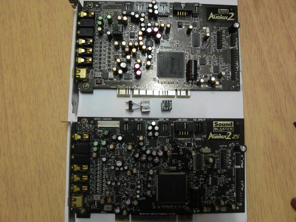
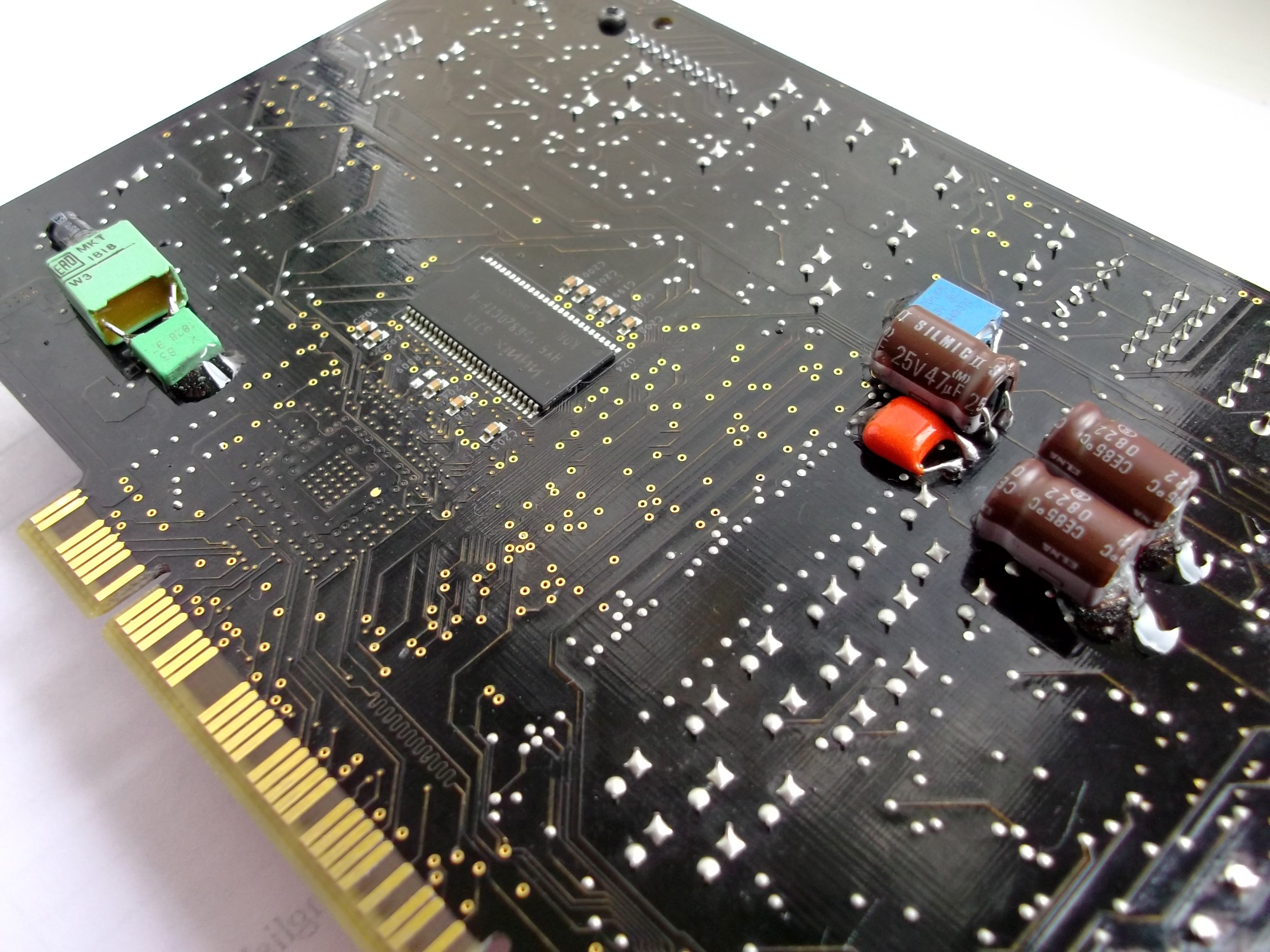
You can create hybrids by using Nichicon ES on the ELNAs. They are not as good as the films but smaller in size with slightly different characteristic. The ES is not the top category from Nichicon still NP electrolytes have their special reputation for audio. As I see your cards are not short on Nichicon FG and all the bigger caps Silmic II, so you may do better with the film capacitors.
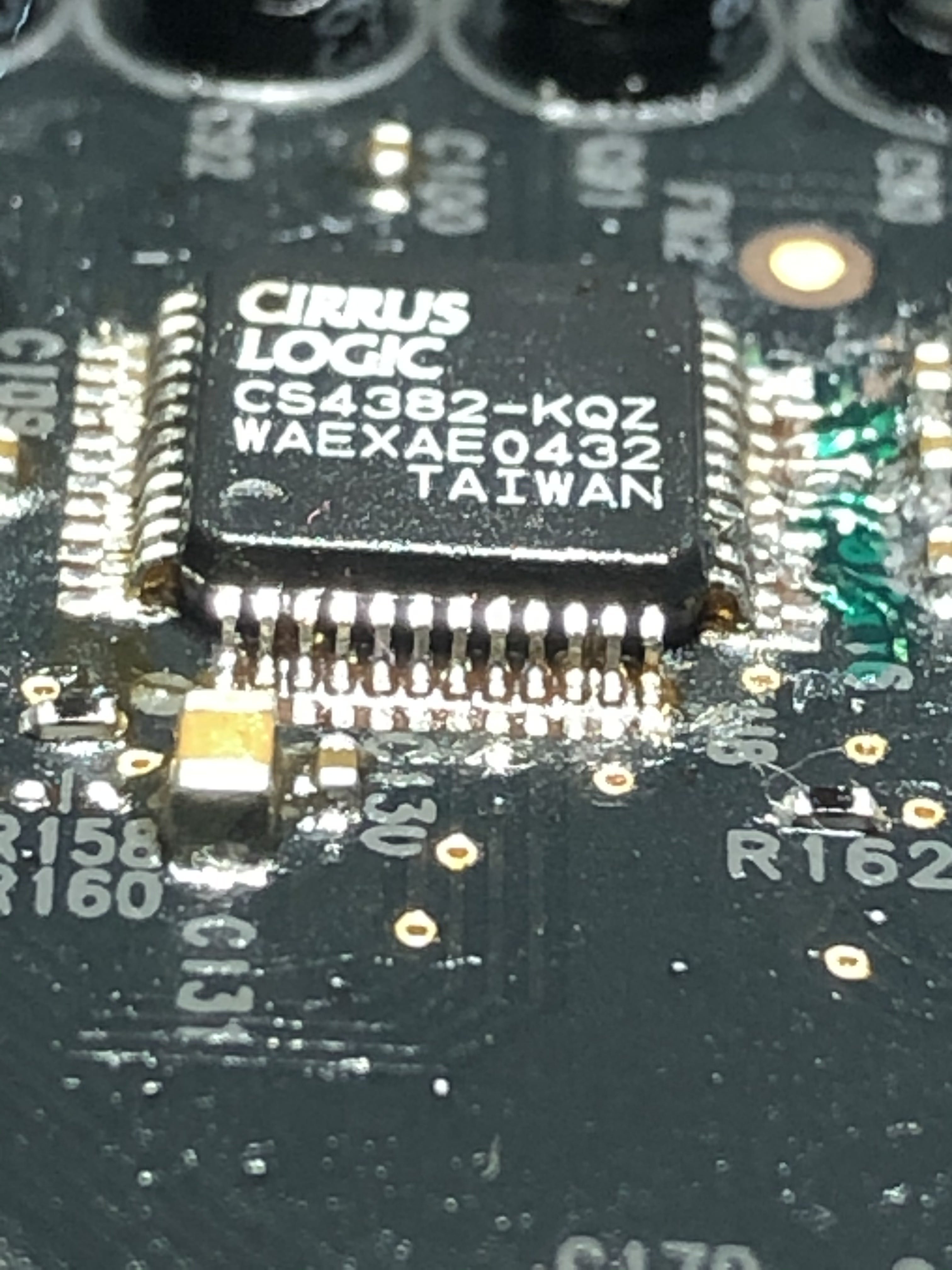
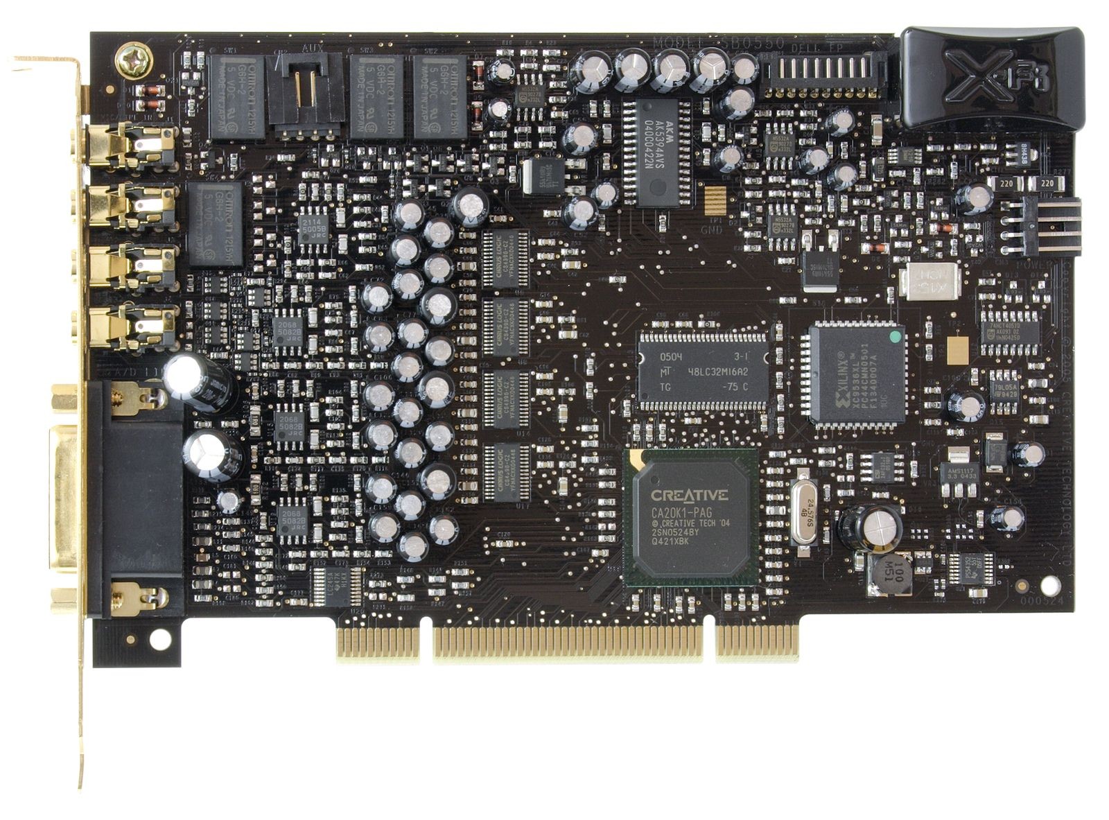
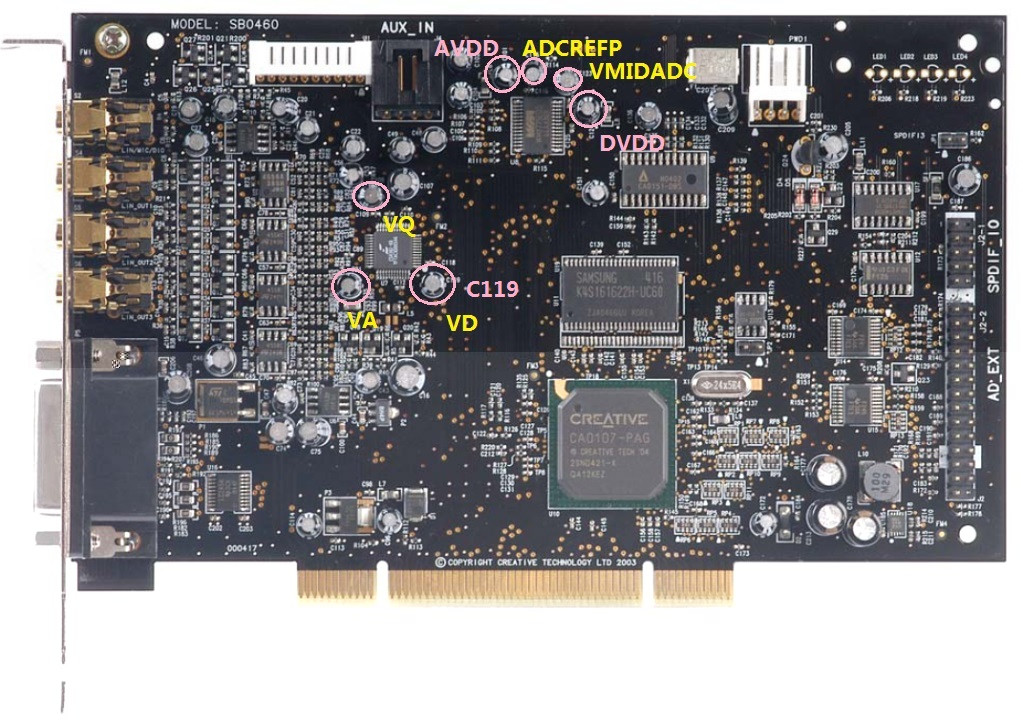
 
Jul 29, 2016 at 11:51 AM Post #122 of 154
@ramachandra
 
Now that i have 2 Elite Pros (one stock and one moded) i did some side-by-side testing and experimentation, and these were the results:
 
I know that you had some doubts about the main power cap regarding bass.. and here are my findings:
 
Stock 220uF G-Luxon (esr=0.09 ohms)
vs.
1000uF@6,3v Pana.FC (0.09)+ 100uf@6,3v MURATA Ceramic (0.002) (edit:1000 not 1500)
vs.
330uF@16v Pana.FM (0.056)
vs.
330uF@16v Pana.FM + 100uf@6,3v MURATA Ceramic
 
Bass: no audible difference
Clarity: OH YEAH!
bigsmile_face.gif

 
felt no real difference with or without the ceramic.. also felt almost no diff btwn FC & FM .. FM maaaaybe a bit better.
But i could say that this mod alone made the stock card sound almost as involved/detailed as my modded one... almost.
(Later Edit:
I think there needs to be a balance between ESR & Capacity. Like if they have the same ESR but different capacity, the one with a bigger capacity will charge slower, coz there's more of it to charge at the same rate/resistance.) 
 
I couldn't make the stock card work with the original CD drivers that i was using (still has dead line-in/mic/aux), so i had to use the website ones for both the cards (so it would be fair). What i immediately felt with my card, was a big boost in lower-bass!
 
Other differences:
On my fully modded one: music is a bit more detailed (and not blended) ... mids & highs are a bit better.. And my personal favorite: the echos give more information about the room where the instrument is played.
But you have to pay extreme attention to be able to hear these differences.
 
other thoughts:
TBH, i have the sensation that this other card (when with original power cap) sounds a bit better than mine sounded when it was stock.. it just might be the drivers, idk.
 
One thing's for sure though: doing all the mods and spending so much money, is not for everyone.
So for someone who wants a quick clean way to improve the card; i suggest trying out different drivers + changing only the main cap (C151 in case of the E.P.) to a Panasonic FM of bigger value (& i see no point in going over 1500uF @ 6,3v-to-16v), and also putting a 0.15uF WIMA mk4 PPFilm (or similar) on the +/- pins of the OpAmps i feel is a good improvement..
 
-------
 
In other news:
I carefully studied the works of the great @bichi himself :) And found out which are the caps for the DACs on the E.P.
The row of 100uf&45uf near the dacs, are:
For 1st DAC:
C40=100uf=(FILT+) to GND - Positive Voltage Reference (Output) - Positive reference voltage for the internal
sampling circuits
C63=45uf=Voltage Reference (Input) - Positive voltage reference for internal sampling circuits.
And upon researching what caps go best for DAC Vref, i found that it needs to be a cap with low VoltageLoss and low esr across a wider band of frequencies.
An never-used 47uF@16v SILMIC II that i measured, has a small Vloss of 0.8%, and @ 0.50ohms esr..  and from what i know, their esr is more linear across a wider frequency than other caps.. So maybe that's why they are good in that spot.
(please feel free to add/correct me)
 
Also i changed C55 - another 47uF@16v CAP - that is responsible for the "Analog V-in" for ALL 4 DACs - with a leftover SILMIC II of the same value.. Didn't notice any audible difference.
The VDD part of the DAC, doesn't have any electrolytic caps on it; the only electrolytic around there is a 22uf@16v (C154) before the 5v-to-3.3v converter that powers the DAC. And that one i've changed a long time ago to a 100uf Pana FC .. which i now want to change to FM of maybe bigger value.
@bichi changed that to 220uF@25v FM, and the main CAP to a Rubycon MBZ, 1500uf @ 6.3vdc (ESR: 0.026) and i think he tested the card with a scope before/after all power modifications.. so might be a good recipe.
 
I still have the crackling issue in some games (although reduced), but that's why i still also want to tinker with the power section.
 
Jul 30, 2016 at 11:37 AM Post #123 of 154
Ramachandra, thanks for your advices!
 
Finally, more different kinds of caps arrived today. I'm going to spend some leisure on testing them with the sound cards to see whether they could generate any possible effects.


Aug 4, 2016 at 9:04 AM Post #125 of 154
To be frank, I know nothing about it and just put some very small value capacitors randomly onto somewhere of the card for an initial trial and error. Fortunately, the sound's not getting worse and to some extent the highs is a bit more detailed and bright.


Aug 14, 2016 at 11:15 AM Post #126 of 154
I think that the --in games-- crackling issue with my card, is more likely to be because it shares the IRQ with 5 other devices (including the Graphics card), in both WinXP & Win7 :-\
After disabling some of the shared devices, the issue is more present than ever.. and also computer sounds (i.e. HDD, ram accessing, etc) can be heard in some games.
I have no way of managing IRQs in BIOS, and only have 1 PCI slot; so i might have to learn to live with this issue..sadly.
 
@TimHKG
If you decide to keep them, you should really shorten the leads on those capacitors..
 
Aug 16, 2016 at 9:36 AM Post #127 of 154
@Foxer
 
By the way, they're still under testing in ways of different op-amps to harmony with different film capacitors at different locations of the cards.
 
Yes, I'll cut short the leads when they're settled down. Thanks for your advice anyhow!


Sep 29, 2016 at 12:44 PM Post #128 of 154
Hello.

I just received an X-Fi Titanium PCIe Card and I am interested in performing the upgrades to this card.  So far what I encountered is that I cannot purchase the following caps going by ramachandras recommendations on the first page:
Elna Cerafine
Sanyo OsCon

 
If Nichicon Caps can be used as an alternate cap for the Elna Cerafines and Sanyo OsCons, what series caps can be recommended as the replacement cap?  If anyone has any of the available caps, would they like to donate the caps I cannot get to get started on my project?

Thanks!!!
 
Sep 29, 2016 at 3:02 PM Post #129 of 154
Hi @DBX1!
 
First things first: If you haven't read the entire thread, i highly suggest you do so! I think that most of your questions will be answered by the conversation that went on here.
 
My suggestion would be to go for Elna Silmic II (in places where there is analog signal, or power supply to analog sections/chips) if you can't find Cerafines.  Cerafines are out of production as far as i know. 
 
Also IIRC, Sanyo Oscon is a solid polymer cap. The Oscon series have been taken over by Panasonic, and are still great caps; but not for audio. I have not tried them myself, but all the research that i've done, points to not using solid polymer caps for audio purposes. 
Myself, i think i will go for Panasonic FM or FR on the rest of the card.
 
Your biggest problem i think will be to find out what caps have what purpose on your card; as there hasn't been much modding done on the Titanium (coz putting random caps in random places, will very likely NOT give the desired result).
Also you might need to know at what voltage the OpAmps operate on the card, if you want to change them.
 
Read the whole thread carefully, and i'll try to answer more of your questions afterwards (if you'll still have any).
 
Good luck!
 
Sep 29, 2016 at 8:50 PM Post #130 of 154
Thanks Foxer.

I was under the assumption that Rama had performed the mods to the xfi titanium as it is noted in his pics, which i am prepared to follow. At this point i have read through the first 6 pages and will complete the rest tonight ot tomorrow. For now, this is what i have gathered from reading the posts so far...

Since elna cerafines are out of prodution, i will take your advice, along with what rama noted in the titanium upgrade to go with the elna silmic ii as an alternative. I have experience with nichicons, where my experience has been positive using them. If i were to use them in the audio section, ii would use fine gold or the kz line if it is recommended as an alternative.

I think i will start wit upgrading the decoupling caps, then later the crystal clock, and then the opamps. I plan to purchase the opamps that is labeled in ramas upgrade path in the xfi titanium.

Any thoughts so far at this point?

Thanks!!!!
 
Sep 29, 2016 at 10:40 PM Post #131 of 154
Your plan seems ok!
I think you will come by a few more details as you read the remaining pages of the thread 
smile.gif

(power filtering caps upgrades are also a "MUST", in my opinion)
 
My biggest advice tho, would be this: Be mindful of the OpAmps when desoldering them! For lots of people, that was the breaking point of the card; as they ripped off the pads. 
I would recommend using A LOT of paper masking tape around them, a paper bag on the rest of the card... and 2 soldering irons at the same time.
To remove the old OpAmps, join all 4 pins on each side with abundant solder (but don't make a mess). 
Then use both soldering irons (one in each hand) to simply pick up the OpAmp, when the solder on each side is fluid.
But before you attempt this, PRACTICE, PRACTICE, PRACTICE on a dead board. 
Using this method i remove OpAmps safely in just a few seconds.
Also as a precaution, unplug the soldering irons right before you use both of them on the card. They can sometimes carry a charge that will go from one iron to the other, and damage components on the card.
After that, Solder Wick is your best friend for cleaning the pads. Use solder only AFTER you've seated the new Opamp.. To avoid accidents, avoid using metal tools; i use a wooden toothpick to gently press on the OpAmp when soldering it back on (using just 1 soldering iron, of course).
Gel type FLUX and a good magnifying glass can make the difference between success & disaster 
wink.gif

 
Sep 29, 2016 at 11:18 PM Post #132 of 154
Thanks Foxer for the advice on how to deal with the Solder/Desoldering of OpAmps.  I did read people having difficulty removing the opamps.  Hopefully my solder skills and solder equipment will give me better fortune than some of those who have had undesirable luck when dealing with their removal of opamps.

Soldering Wick - Check
Temperature Controlled ESD Soldering Iron - Check
Magmifying Glass - Check

Do you have any advice regarding which caps to use for the power filtering caps ?  I want to have a straight answer from those who are experienced with this upgrade rather than for me to just guess and hope.

I am skilled with a soldering iron, I can read a schematic diagram for parts used - voltage and value of component to be used at locations, but my electronic knowledge is limited.  So if you told me to remove those filter caps, or change the bypass caps, or have a look at the coupling caps (or decoupling caps), I know the lingo, but I would not know what such caps are.  So yes, I do try to find out the secrets are on building a better circuit, but I am not familiar with such how to read on a schematic diagram what those caps are for.

Just an fyi - I finished upgrading resistors on a line stage stereo preamp - all that is left are the electrolytic caps.  But I have to gather what the caps on the line stage are used for - if they are bypass caps, coupling, or decoupling, so that I can pick the right caps for the best performance.

But I do know the difference between a film cap, an electrolytic, a polysterenye, tantalum, ceramic caps.  So I am not totally hopeless.  :D

So although my skills are limited, I am not totally lost!!!  :D

If I can gather enough information, I should be able to place an order for parts with Mouser tomorrow.
 
Thanks Foxer.
 
Sep 30, 2016 at 2:49 PM Post #133 of 154
You're welcome :) 
 
I've had great results using Panasonic FM (as a power filter cap for the X-Fi processor). If you want, you can also pair it with a "Murata" ceramic SMD cap. That's what i did.
 
As for the values, i don't know your card.... but as a safe rule of thumb, you can double (or in some cases triple or quadruple) the capacity of the old electrolytic cap.. and the ceramic should be around 1/2 (half) of the old electrolytic. Keep voltages the same as the old one, if you are not sure.
 
Now, i don't know if the Titanium has a main power filter cap.. but being the same X-Fi chip and all, it still needs 1.25V .. so it will draw it from the 5V pin of the PCIe and use some type of switching power supply chip, to turn that into 1.25V.. with at least a cap in front of the power supply chip, and at least a cap behind it.
 
When we refer to the "main power cap", we refer to that cap that is after the switching power supply chip; so it's the cap that filters that 1.25V that will go to the X-Fi processor (and in the case of the Elite Pro, it's 220uF @16v)
In the case of the Elite Pro, there is also a little power cap (22uF@16V), that's before the Switching power supply chip (Ti PS54352), that filters 5V power from the PCI 5V pins.. And i replaced that cap with a 100uF one.. and maybe will replace it again with a 220uF one. That cap assures clean power to not only the Switching PSU chip, but it also goes to other places, like the digital side of the DACS (iirc).
 
My advice would be to not rush. 
It took me a few solid months of research before i figured things out. Not to mention how many times i thought that i gathered all the knowledge i needed for the project, only to discover the following week something that completely changed the game.
Tbh, even now i'm not sure of certain aspects.. but such is life 
smile.gif


P.S. Don't go over 400C when using the irons on the OpAmps. And don't heat the heck out of them.
 
Oct 3, 2016 at 9:09 AM Post #134 of 154
Thanks much for your advice Foxer.

I will look into this and will place an order for some caps, a crystal, and OpAmps.  Hopefully, my results will be as successful as yours.

I have a question for you in regards of what you posted about the Power Filter Cap - which I will look into to see if my card has it:
"As for the values, i don't know your card.... but as a safe rule of thumb, you can double (or in some cases triple or quadruple) the capacity of the old electrolytic cap.. and the ceramic should be around 1/2 (half) of the old electrolytic. Keep voltages the same as the old one, if you are not sure."

I understand what you mention that its OK to double, triple, or quadruple the value of the cap.  But one thing I do when replacing electrolytic caps, I usually double or triple the voltage value as well.  If room to fit the cap is not an issue, should I not be doing this?  I have not seen (or heard) any ill effects when I perform this on components in my stereo system.

As always, thanks for your input Foxer. 
 
Oct 4, 2016 at 11:59 AM Post #135 of 154
Regarding Capacitor voltages, the opinions are divided..  Some people say that there's no harm in using larger voltage caps, other people avoid doing that because the fact that the larger voltage Cap might loose it's efficiency if it gets a voltage that is too small in comparison to it's "capabilities".
For me, a good rule for electrolytics is that the cap should be rated at least 50% higher voltage than the circuit's voltage, and not more than 400% (4x). For instance: if you have 3.3V you can safely use a 6.3V Cap. But if you have 5V, you better use a 10V or 16V Cap.. and i would  only go higher if i need better ESR (a higher Voltage or uF Cap has better ESR).. but my beliefe is that some efficiency will be lost the more i will up the voltage. After what percentage will that "efficiency" start to matter? I have no idea..
 
For the X-Fi chip (that is powered with 1.25V), on my card i experimented replacing the original 220uF@16v Cap, with caps from 1000 to1500uf @6.3V .. And the MURATA Ceramic is 100uF also @ 6.3V. Because 6.3V is already almost 300% (3x) of the 1.25V that will actually go through it. A 16V cap in a 1.25V circuit, to me it just seems stupid. (On the other hand, a ceramic cap, needs to be AT LEAST 2x larger!) 
CREATIVE used a 16V Cap there, because it was cheaper to use crap caps with larger voltage, in order to obtain good ESR; than to use good quality expensive caps with high ESR at proper voltage for that place. 
I also tried a combination of Panasonic FM 330uF@16v + Murata 100uF@6.3 Multylayer Ceramic, on another Elite Pro that had no other modifications, and the clarity of the sound was heavily improved! (I think i wrote about it here on this thread). It's believed that if you up the uF on the power cap, you will get better bass.. but i wouldn't go overboard, as it has happened to some people with a TOO LARGE capacitor in that position; the card wouldn't get detected any more when plugged back into the PC... (probably because there wasn't enough power left for the X-Fi chip, after powering the huge cap
tongue_smile.gif
 ) 
After all.. every cap should ideally be calculated to properly suit the circuitry.. So because we can't do that, we have to make sensible changes, not extreme ones.  
 
Personally, on your card i would keep the same voltages.
 
And if you do decide to use ceramic Caps, be sure to get ones with a good rating, like X8R or X7R or X5R. Don't go under X5R
 

Users who are viewing this thread

Back
Top