


AndrewFischer
500+ Head-Fier
- Joined
- Dec 7, 2003
- Posts
- 574
- Likes
- 10
Thanks for taking the time to redo the measurements.

| Originally Posted by Sinbios /img/forum/go_quote.gif Quick question, what happens if Vin is below Vout for the regulator? Does it work in pass through mode, shut down completely, or actually add noise? |
| does anyone have any spare regulators, knows of a place I can order them online or any alternatives that would work? |

| Originally Posted by AngryGuy /img/forum/go_quote.gif So, I want to make one of these but it appears I'm a bit late to the party. Is anyone still selling all the parts needed for it, or a kit or something? |
| Originally Posted by error401 /img/forum/go_quote.gif HeadFier jrossel has apparently gotten permission from amb to provide kits and raw PCBs for this project. |
| Originally Posted by amb /img/forum/go_quote.gif Not me, but it was alf. Apparently jrossel is getting pcbs manufactured so hopefully they will be available again soon. |
| USB device not recognized One of the USB devices attached to this computer has malfunctioned and Windows does not recognize it... |
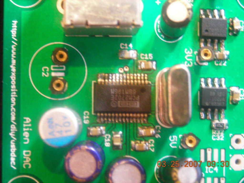
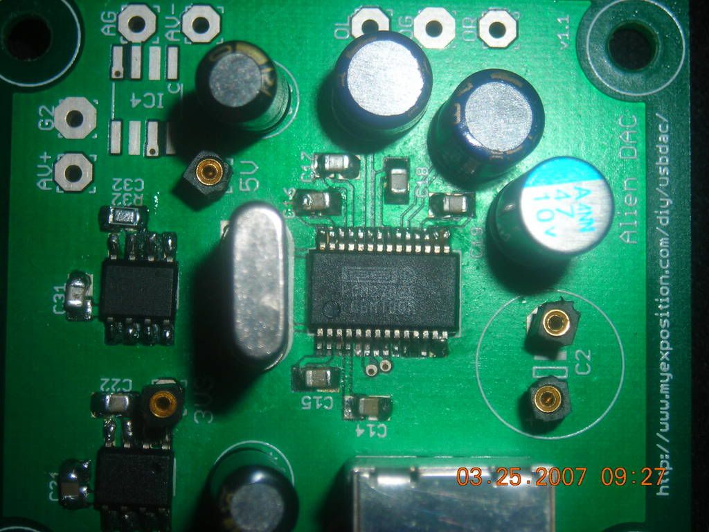
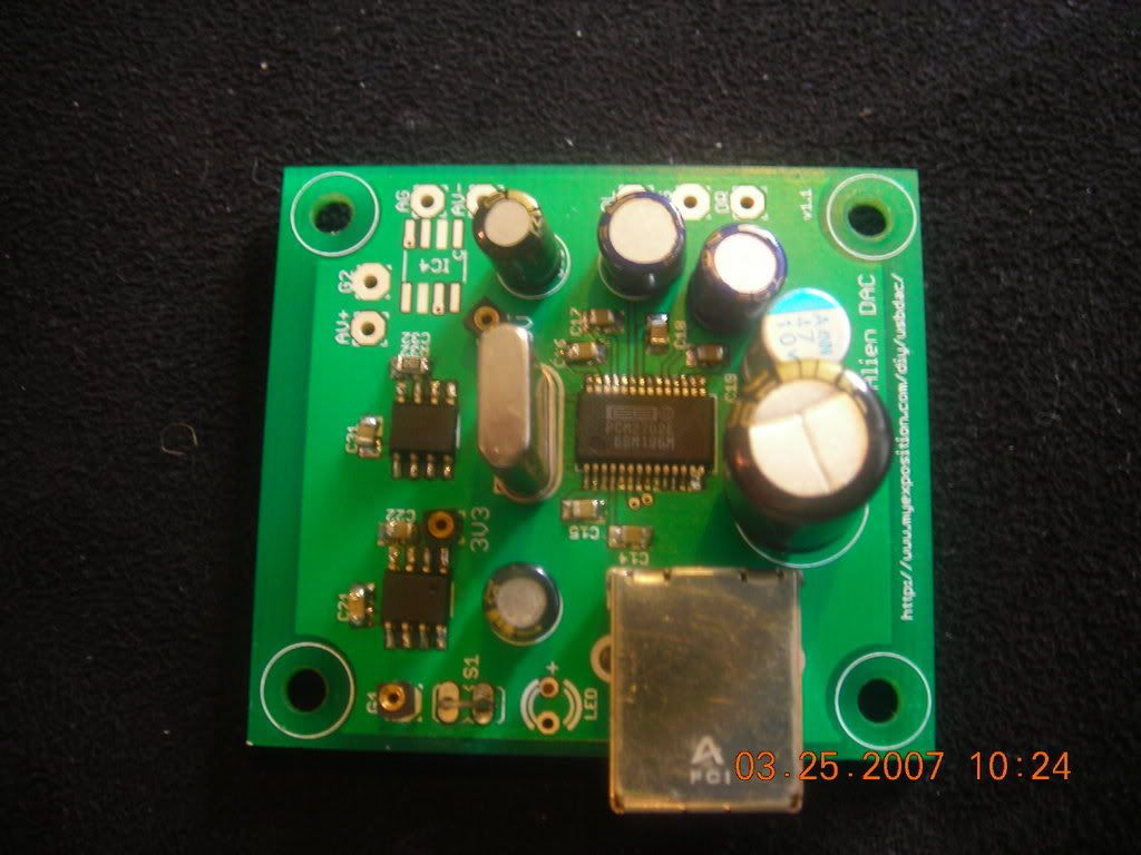

| You may have some solder bridges on the dac chip. Looks like pins 27 and 28 may be bridged. Maybe 25 and 24. hard to tell from the photo. You could try some flux and solderwick and try and pick up some of the extra solder. I'd also check all the pins are connected. I had to reflow solder on both of mine. If all else fails, remove the 2702 and try again. I used 3 chips to make two working DACs. |
