Alien DAC v1.1 Construction Thread
May 4, 2007 at 11:26 PM Post #721 of 1,562
Quote:

Originally Posted by FallenAngel /img/forum/go_quote.gif
Good idea to have the board photo handy


I have to admit that I did reference that image and while I thought it looked unconnected, I can also see a line which shows it is. Maybe I am looking at the bottom trace?
 
May 14, 2007 at 12:33 PM Post #722 of 1,562
Quote:

Originally Posted by Calroth /img/forum/go_quote.gif
Question about the virtual ground option.

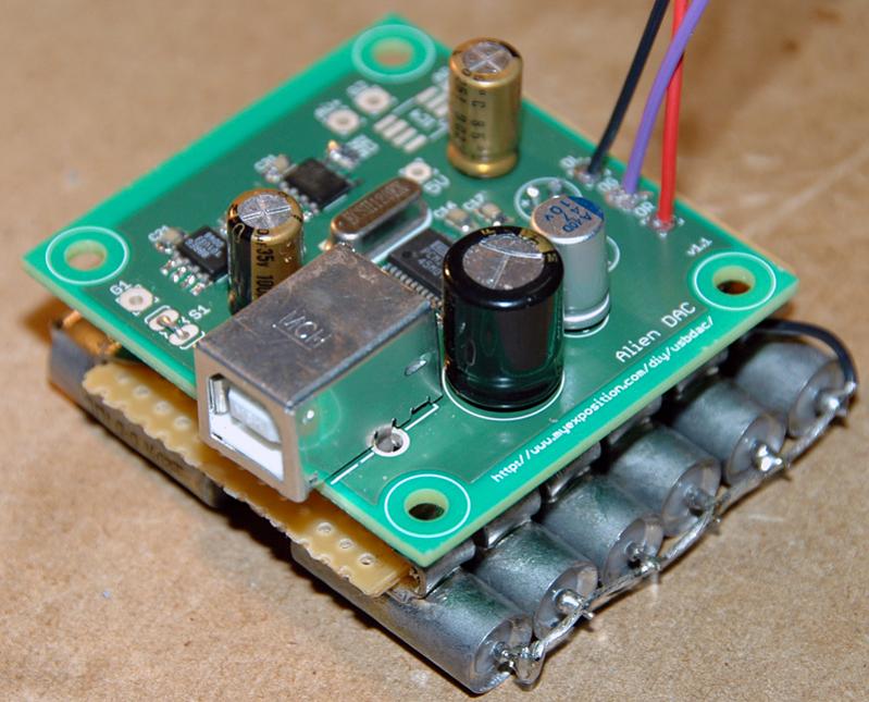
I'm hooking an Alien DAC up to a PIMETA. So I'm wiring up AV+, AV- and AG.

AV+ and AV- is fine. But I'm confused with AG. On the PIMETA, that's connected to input ground, which is connected to the Alien DAC OG. So if I wired that, then I would be effectively connecting AG to OG (and the rest of the ground plane).

Is that right, or am I missing something?


Right, I posted that a month ago, and in the meantime have been trying to wrap my head around virtual ground theory. As a primer: I have an Alien DAC, a PIMETA, and an OPA551 to act as the IC4 virtual ground buffer between the two. It's all to run on a 12V supply, split into +6V, 0 and -6V.

The first thing I tried was what I described above: connected the Alien DAC OG to PIMETA IG, and the Alien DAC AV+ to the same. It pulled the entire virtual ground on both sides up by 4V... so we were +6V, +4V and -6V. That ain't right, Calroth. So back to Tangent's virtual grounds page.

So, after some critical thought, I decided that the Alien DAC's ground should be buffered and isolated from the PIMETA's, though still at the same voltage. So, disconnected the Alien DAC OG to PIMETA IG (leaving the left and right channel wires there). Now, the Alien DAC's ground is buffered. In theory, its current draw etc. shouldn't disturb either ground level. And it didn't... much. The PIMETA's ground stayed at 0V, so the OPA551 was definitely isolating the Alien DAC. However, the Alien DAC's ground was offset by +170mV. Better!... but still unacceptable.

Scratched my head. Then did what every self-respecting DIY'er would do: I Mini³-ified it! Added a 600R ferrite on the output of the OPA551, outside the feedback loop - plenty of spares from the Alien DAC construction. I had to lift a few pins to do it. You don't want to see the board... between this and all the other things I tried, it ain't a pretty sight. But, the ground is now offset by about +19mV. Yeah, that's close enough for me! Hooked it up and got it playing music.

So. Having read all that... any comments? Did I do something completely stupid? Next thing to try is putting some 100nF bypass caps on the OPA551 V+ and V- (also left over from the Alien DAC build). The datasheet suggests it, but I think that's just a precautionary thing. Also, I suppose I could shift the DC blocking caps from the Alien DAC to the PIMETA to wipe off that last bit of offset.
 
May 14, 2007 at 6:25 PM Post #723 of 1,562
just took an attempt to build this dac in one afternoon with no luck. It is my first try of smd soldering , my tweezers are too stiff when I tried to grip RLED to its postion, it jumped up and pew, disappear in the air, never found it again.
blink.gif
save for me a LED.

When I finished soldering and plug it to computer, I spot some little sparks at around pin 24-27, not sure exact where, then I unplug it and tried to clean the bridges and plug to computer again, no sparks, and the computer did not response either. After a few second, pin 25(i thought), which is VCCL get so hot that the residue of flux start smoking, so I guess I got some where short around this pin, but will this be the reason the computer do not recognize? I read some thread say that when the computer does not recognize, it is more likely something wrong at the 3.3V side.
I put some pictures here and hope some one can take a close look and spot the flaws.

 
May 20, 2007 at 1:37 AM Post #727 of 1,562
hope you guys can help

put one of these together the other day and i'm just testing my voltages. 3.3V is at 3.3V but my 5V (which should be 5.4V as I chose resistor values for OC) is at -1.4V? Any ideas? I've got my c32 in place where it says c32/r32 and my r32 where it says c32 on the reverse side. i just figured these were in paralel and it doesn't matter which way around they go. yes no? =S

cheers

dave
 
Jun 4, 2007 at 1:07 AM Post #730 of 1,562
I successfully built the Alien DAC, but I have hum that seems to be from the oscillator. Using a head phone amp connected to the DAC with the DAC only connected to a 9 volt battery and not connected to a computer, I get hum. If I remove the battery supply, the hum goes away. If I connect the DAC to the computer, it works, but the hum is still there. I originally did not use the ferrites, but added them when I heard the hum. This seems to have reduced the hum only marginally.

Suggestions on where to begin are appreciated.
 
Jun 7, 2007 at 1:56 PM Post #733 of 1,562
Virtual Ground / IC4

I too am confused as to how to use IC4 to power the Alien DAC using the virtual ground from another module. OG to IG? Or ?? Cannot figure it out from the schematic.
 
Jun 8, 2007 at 12:32 AM Post #735 of 1,562
Quote:

Originally Posted by pkshiu /img/forum/go_quote.gif
Virtual Ground / IC4

I too am confused as to how to use IC4 to power the Alien DAC using the virtual ground from another module. OG to IG? Or ?? Cannot figure it out from the schematic.


OK, here's what I connected. If someone with more experience can explain more, please do. This is assuming that your amp's virtual ground is tied to its input ground, which is the case with most designs I've seen.

For the power supply section:
  1. Amp V+ to Alien DAC AV+
  2. Amp V- (or ground) to Alien DAC AV-
  3. Amp virtual ground to Alien DAC AG
For the signal section:
  1. Alien DAC OL to amp IL
  2. Alien DAC OR to amp IR
  3. Do not connect Alien DAC OG to amp IG
Check the voltage offset that IC4 generates between AG and the ground plane, it should be minimal. You might need to do things like adding bypass capacitors or ferrites to IC4 to get the offset down.

I also recommend testing with a 9V power supply to begin with, which will split into +4.5/0/-4.5V. So that in the worst case (virtual ground collapse), you won't exceed the 10V limit of the REG101 chips. Of course, if you have 6.3V capacitors in the power supply path (I can't remember if there are any), you might damage those. Exciting times.
 

Users who are viewing this thread

Back
Top