A Stanton Dynaphase 60 Project
Oct 23, 2017 at 11:48 AM Thread Starter Post #1 of 19

WallofHooligans

100+ Head-Fier
Joined
Feb 8, 2017
Posts
331
Likes
136
Hello, my dudes. I figured I would detail one of my goings-ons and ask for a bit of feedback.
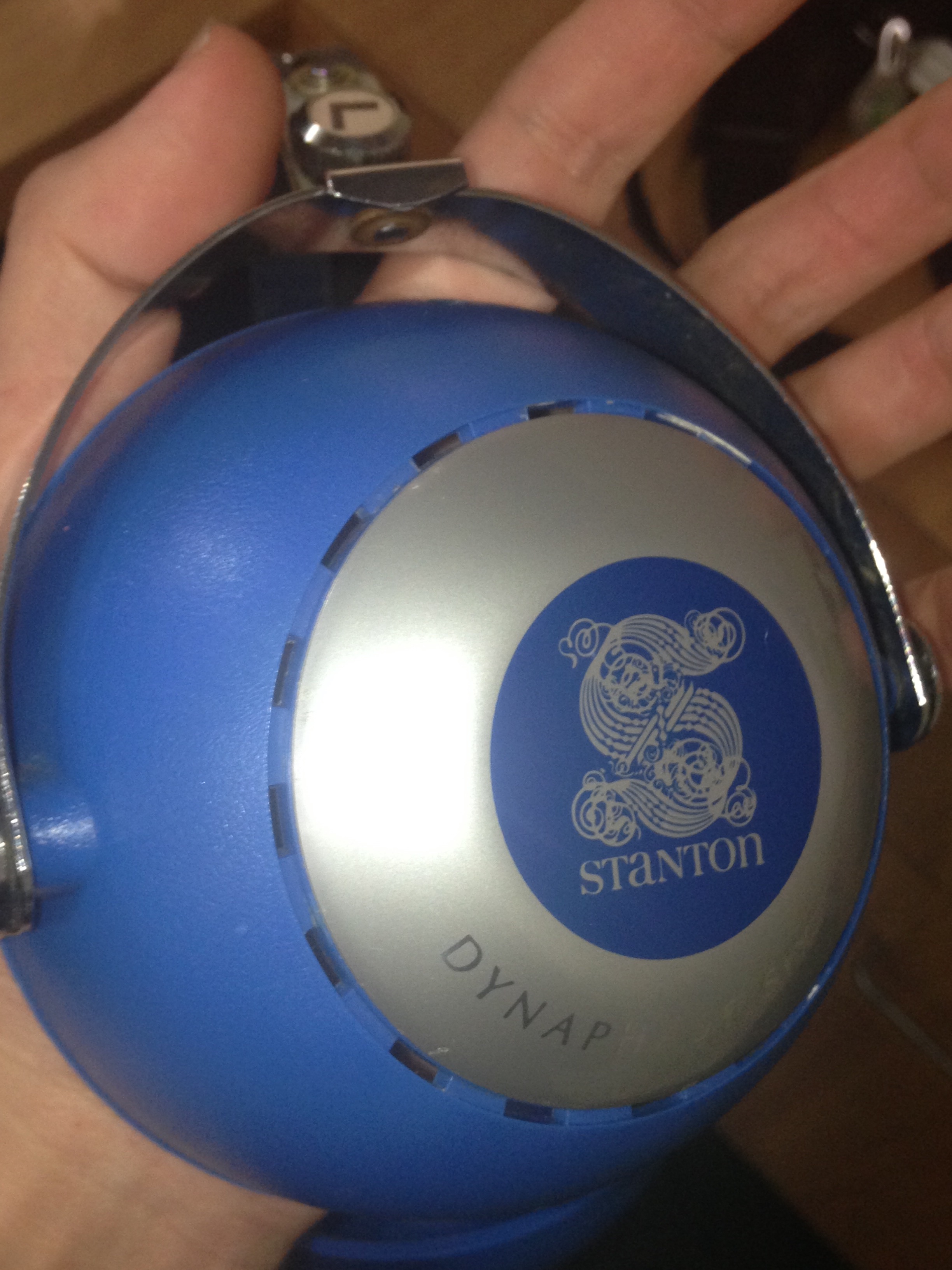
Recently, I spied a heavily beaten and battered Stanton Dynaphase Sixty on the ebay. Now, I already own a pair in great condition and I absolutely love it. There's just something about the huge soundstage and sapphire coloration that tickles my fancy. Not to mention the old Stanton logo has it's own beauty, and the idea of a two-way headphone really piques my interests. I've become almost entirely an orthodynamic/planar magnetic purist, but these Dynaphase cans just activate my almonds, if you know what I mean. They get my noggin' joggin'.

Let me start by showing off what we're dealing with here so you can see what square we're starting at before we play.
s-l1600.jpg

OOF, that's a haggard pair of cans. But they are even worse than they look from this image. Here's the skinny on some smaller details.
s-l1600 (1).jpg s-l1600 (2).jpg
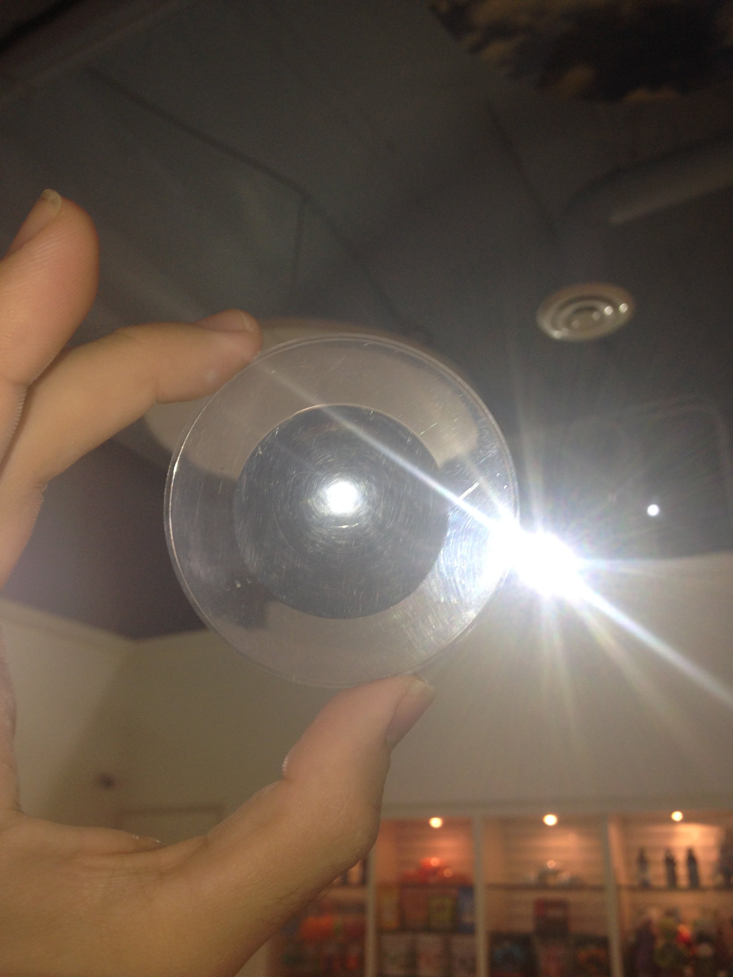
Yep, those are the earpads.... but with the padding and the top layer pulled out entirely! Ripped asunder like a dry potato through a table saw! There's a hidden bonus here- upon pulling off the useless earpad bits, I found an entire edge of crushed plastic contained in it. There's a chunk of flat plastic missing from around 30% of the circumference. That means that it's impossible to get a seal, and the sharp edges pose a threat to new earpads. I'm not sure how to rebuild it, but I'm much too stubborn to cut my losses!
s-l1600 (5).jpg
Here's the cable and plug. It's not the standard termination, and the part itself doesn't seem to close correctly. It's a bit rusted and whatnot. The cable isn't supposed to be such a dusky blue, and all of the heatshink strain reliefs are missing. I'm not too worried about these bits, I plan on doing something fancy as a replacement.
s-l1600 (4).jpg
Yep, the headband is totally ruined too. The original (admittedly sort of crappy) pleather is totally bound from one end to the other in sticky old electrical tape. I didn't even think about this one, I cut the sucker off end to end and trashed it. The insides were exposed and the foam had a bit of decomposition going on, which is why they probably bound it in tape. Yuck. Strangely though, these things don't have the usual "oh they've been in grandpa's basement for 40 years" smell. I wonder what these things have seen. The last owner had done a few quick fixes to these, a super glued strain relief, the non standard termination and bound headband, not to mention the slight fading of the blue plastic on the upper ends of the cups... I imagine that these must have been well used for many years. I'm going to do my best to reanimate this puppy, and modify them to my liking.

Edit*** These first pictures are shamelessly stolen from the ebay seller***
 

Attachments

  • s-l1600 (3).jpg
    s-l1600 (3).jpg
    184.1 KB · Views: 0
Last edited:
Oct 23, 2017 at 12:24 PM Post #2 of 19
So here's what's happening with the stuff right now. I've disassembled the cans almost entirely. The cable was first to go- I grabbed some scissors and put that dusky cable 6 feet under. Here's what's inside the assembled can. The left cup contains the source cable, a (Left) pathway across both the paper cone woofer and the dome tweeter. It has a transformer for the crossover bound in green wire. The right side transformer is bound in reddish copper wire. The crossover has one big ol' 47 microfarad cap rated for 16volts. Across from the crossover assembly is a very simple jump point for the right pathway, where the same crossover and double speaker format exist. Look at that "circuit board." It's just a slab of plastic with some metal hole punched tabs and blobs of solder. Incredibly simple.
IMG_3809.JPG
Out of curiousity, I opened up the speaker assembly itself and found a few things that I would like to address. I've never seen anyone go this far into the device, so let me show it off. Here's what's going on underneath that big paper cone!
IMG_3800.JPG
I'll get better pictures of every singular part before I re-assemble it. These pictures are awfully blurry, my bad! By the way, I was able to pull this thing out by very diligently poking holes in the adhesive with the sharp end of an x-acto blade. Be super careful and don't rush, cause you don't want to shatter the blade or something dumb like that. I actually lost the tip of mine right at the end. You could probably try some sort of paint thinner to dissolve the glue, but I was afraid that I might get some on the paper cone. Anywho, here's my first point to modify. The paper cone itself is spaced from the enclosure with an incredibly simple ring of thick paper. Probably the same composition as the actual speaker dome itself. I didn't like how powdery and dry rotten that bit had become, so I sliced it off.
IMG_3813.JPG
Now the plan is to find a suitable alternative. I'm considering something like an o-ring or maybe some simple blue tack around the rim in an equal spacing. This little bit is important only to keep the paper cone sealed and snug. Not sure what I'll end up using, but that's gotta go.
So I can use feedback at every stage, give me your opinions as I continue, please.
 
Oct 23, 2017 at 12:56 PM Post #3 of 19
On the exterior, I've taken everything apart. It's interesting how these things were built- They really put a lot of care and unnecessary complexity into this design. I love it.
Here it is before any cleaning has taken place. The band is rusty and pitted. I'm trying hard to address that, but pitting is very hard to fix.
IMG_3791.JPG IMG_3787.JPG IMG_3792.JPG
On the sides, there's an assembly of plastic lens, dry, thoroughly dead spacer and a metal rim to hold it in place. Here's what that looks like from the inside (notice the four folded tabs), with all three parts laid out and how the side looks exposed.
IMG_3794.JPG IMG_3795.JPG IMG_3793.JPG
The plastic lenses are heavily scratched in multiple directions at multiple depths. It's hard to show off without turning it in the light, but here's a bad photo of what I've got.
IMG_3786.JPG
Things to do at this stage:
1) Clean everything. Lot's of Brasso and polishing cloths, papers, cleaners and whatnot. I'll get some nicer pictures of what I've got after I make some headway. If you guys have tips on getting some of the pitting in the headband out, I'd appreciate any suggestions.

2) Attempt to remove the scratches from the plastic lens. I've tried a lot of random stuff up until now, and not much helps. 2500 grit sandpaper under flowing water just made it cloudy. I'll try to move up to a higher grit.

3) Consider how to modify the headband. I plan on doing something snazzy to make it a double headband system. Sort of like the elastics on an AKG or something similar.

4) Drill a hole in the right cup. I don't want both channels to be fed through one side anymore. These are much too heavy to keep the imbalanced cable.

5) This one depends on you fine onlookers- this brick of metal on top of the speakers is what makes these things so damned heavy.IMG_3807.JPG
I've poked it with some iron- it's not magnetic as far as I can tell. That little black cylinder sitting inside it is the magnet. I'll get a better picture later so you can see what's happening- but do you chaps think that the metal is necessary? It seems to be acting as a brace to keep the black magnet affixed and sitting in the right direction, but surely there's a better way to do that? I'm not sure. Maybe there's another function here, maybe someone that knows about classic speakers could give me some information.

6) Change the caps. Self explanatory, but I'm not sure where to start. I want to get something that won't cost too much, but I've heard some bad things about standard electrolytic caps. I don't really understand how to attach an electro + film cap in parallel, and I wouldn't know where to get reasonable replacement film caps in that rating. Again, feedback needed.
 
Oct 24, 2017 at 3:02 AM Post #4 of 19
hmm interesting stuff.

For the plastic lens try cd polish ( the finest you can find ) or hit up a local plastics shop ( we have Industrial Plastics here ) for a special polish.

Have you considered a small bottle of that paper cone treatment for speakers? The stuff that soaks in and creates a plasticized embedded result?
There are likely a few types.

For sure find a new equivalent value BIPOLAR capacitor ( it is likely bipolar but double check if there are any markings at all )and replace that old one, the new caps technology has improved greatly since then ( as you may know ).
Nichicon or Elna are solid but then there are the boutique bipolar things around. If you have the room for those. If you are worried about them maybe increase the voltage rating. I doubt they would fail it's not like its getting massive power. I use em in amps here ( the Elana BP )
You could plug into a speaker crossover calculator ( is that first order crossover I think it might be ) to determine what value you might want to toy around with there, higher or lower to select the frequency range the bigger driver will deal with.
Maybe check the single mylar speaker by itself to see what it is capable of and the big one also by itself to get a feel for what you think each should be dealing with.?
I tweaked the crossover cap in those Sharkk Bravo things in an extensive fix-mod to isolate the electret driver better.
I get stuff from PartsconneXion usually, but that's because it's easy to get a few things at once.


If you want to get crazy on the metal polish you could use some rouge compound and a buffing wheel, worst case some of the pits may remain but polished up well might not be noticeable.
Autosol polish can get messy, but anything will obviously.

That TRS end sure looks like a Switchcraft model. Still available to maintain the stock look. Mogami and/or Canare make a 4 wire blue sheathed cable. You will have some for rewiring the inside too.


it's late and I probably didn't think close enough on this, sorry.
 
Last edited:
Oct 24, 2017 at 3:42 AM Post #5 of 19
I've heard only a few little things about treating paper cones. Most people seem to think that adding additional mass might change the FR in a bad way. I like the way the standard setip sounds but I'm interested in maximizing every aspect that I can. There's also a few oddball ideas floating around for treating paper cones, I've heard people have used liquid shoe polish with good results. On another note, the paper cone that's in here seems higher quality than anything else I've worked with out of a headphone. The backside has an interesting rippled texture, almost like tightly woven cotton.
The cap value is probably perfect where it is, the sound is semi bright, but the bass is huge and kickass. It's a really groovy combo. If there's any way to do it, I would like to pull more sub bass out of the paper cone. I believe it to be possible. I just don't know too much about picking capacitors. I'm an electronics layman, I understand generally what the parts do, but not how same parts compete.

Speaking of inadequate knowledge, I'm considering messing with the tweeter. The impedance value of the tweeters should be matched to whatever else I want to put in instead, right? I think an sfi would actually fit in here. Hopefully the tweeter comes at a standard impedance value so I won't have to mess with the crossover transformers at all.
Edit*** The tweeter comes in at about 7.6ohms and the woofer sits right at 8. The height of the tweeter is just over half an inch, or around 1.5cm. An akai ortho tweeter is 1.1cm tall. The width of the tweeter is about 1.6 inches or 4 cm. The ortho is also 4cm wide!

I'm not worried about how the cable is terminated, though I do appreciate the information about whom is making blue cables!
 
Last edited:
Oct 25, 2017 at 6:16 AM Post #7 of 19
The cleanup process is moving along swimmingly, albeit a bit slowly. Polishing the metal is the easy part, so from afar they are looking nice, but the details just don't reflect quality. There's a lot of pitting on certain parts. I'm not sure that they are fixable without sanding the absolute heck of of the metal, and who knows what kind of metal construction this headband is. Could be plated in shiny metal, and if I go too far I'll end up with something much worse. Anywho here's some progress pics.
IMG_3820.JPG
IMG_3821.JPG IMG_3822.JPG IMG_3826.JPG
IMG_3827.JPG There's some weird cloudiness on the band where the headband used to be. I tried sandpaper and all sorts of things, but it doesn't seem to want to come off. Very strange.
IMG_3829.JPG
IMG_3830.JPG
Look at how pretty the Stanton insignia is! Now you understand why I want to clean up the plastic lenses. I've made some headway on those as well.
IMG_3819.JPG


The nitty gritty starts as soon as I order new capacitors, so stay tuned. And as always, feedback is much appreciated.
 
Oct 26, 2017 at 12:40 AM Post #8 of 19
I wonder if you could buff the lens with some high quality car wax ( the clear stuff ) to get the minor scratches out and shine going.
Best to test that on another piece of plastic first if you try it.

Looking good so far, that's a lot of work.

Oh another option ( or do both ) maybe you can track down some of the car headlight lens restoration treatment or figure out what they use/the best thing for that.
 
Last edited:
Nov 3, 2017 at 2:05 PM Post #9 of 19
I've been considering getting a set of these to do myself... Staying posted to see how the electrical goes.
 
Nov 9, 2017 at 5:38 PM Post #11 of 19
I just recently replaced the caps on my Sixtys. I got some nice Nichicon ones off Mouser and they work wonderfully.

Unfortunately, I can't really help with the drivers themselves as all I did was replace the knackered old grey capacitors and installed an XLR plug so I could detach the cable. I'll be watching this thread closely to see what you come up with!
 
Nov 10, 2017 at 7:49 AM Post #12 of 19
5) This one depends on you fine onlookers- this brick of metal on top of the speakers is what makes these things so damned heavy.
I've poked it with some iron- it's not magnetic as far as I can tell. That little black cylinder sitting inside it is the magnet. I'll get a better picture later so you can see what's happening- but do you chaps think that the metal is necessary? It seems to be acting as a brace to keep the black magnet affixed and sitting in the right direction, but surely there's a better way to do that? I'm not sure. Maybe there's another function here, maybe someone that knows about classic speakers could give me some information.

Can you post a side on picture of the magnet and metal setup? I would be surprised if the behind and wrapped to the side of the magnet is not magnetic. Wrapping a cup of magnetic material around a magnet is an extremely effective way of increasing the magnetic force from a magnet as it redirects the magnetic field from the back of the magnet to the front. If it is a cast aluminum part, I would assume that it is there to keep the magnet in place. If that is a rare earth magnet, it looks pretty thick so use caution if you remove it. It will have a pretty high force and you are going to need a fairly beefy brace to hold it.
 
Nov 10, 2017 at 1:13 PM Post #13 of 19
So here's the assembly from profile. The folded metal box thingy that seems to be keeping the magnet straight looks welded shut and has no magnetic properties whatsoever. It's actually thick enough that resting the head of my screwdriver over it (as in the picture) produces no results.
IMG_3887.JPG

Here's how the assembly looks attached though- There's stubborn old glue on each side of the metal box.
IMG_3884.JPG IMG_3885.JPG IMG_3886.JPG
IMG_3886.JPG


Oh yeah- here's a little shot of the paper cone itself. The backing isn't the same texture as the dry pulp stuff on the front of the cone. Dunno if this is standard, but it seems pretty high quality. I imagine that this stippled surface gives it some extra rigidity.
IMG_3890.JPG
 

Attachments

  • IMG_3889.JPG
    IMG_3889.JPG
    3.8 MB · Views: 0
Nov 10, 2017 at 2:23 PM Post #14 of 19
Yeah the way that is built it wouldn't be magnetic since it wraps all the way around the magnet. It will basically short out the magnetic field. No idea what is going on there to be honest. Cause it looks like a three piece assembly inside that metal part.
 
Nov 10, 2017 at 6:43 PM Post #15 of 19
Yeah the way that is built it wouldn't be magnetic since it wraps all the way around the magnet. It will basically short out the magnetic field. No idea what is going on there to be honest. Cause it looks like a three piece assembly inside that metal part.
Apparently the metal box part is somewhat common on out of date speaker cones, but I don't really see the point. Maybe the capacitor that they used on their boards is magnetic, and the box shields it? I'll check that out when I replace it. The only reason I can think of for it is to brace the magnet and keep it from loosening and falling off, which I've heard of happening in other headphones.... But it's so much extra weight- I imagine you could do the same thing with plexiglass and epoxy...
But anywho, I think I'm going to go ahead and attempt to take it apart fully. The glue is super stubborn though, so it's going to take a ton of patience.
 
Last edited:

Users who are viewing this thread

Back
Top