


- Joined
- Jun 20, 2001
- Posts
- 11,022
- Likes
- 6,595
This is part of a post I made some time ago in another thread, but I thought I'd re-post it here. Take a look at some of the headphone measurement systems (below) that you've been checking out graphs from.
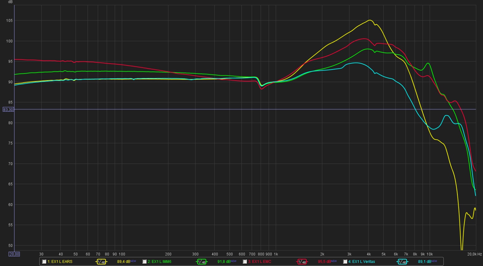
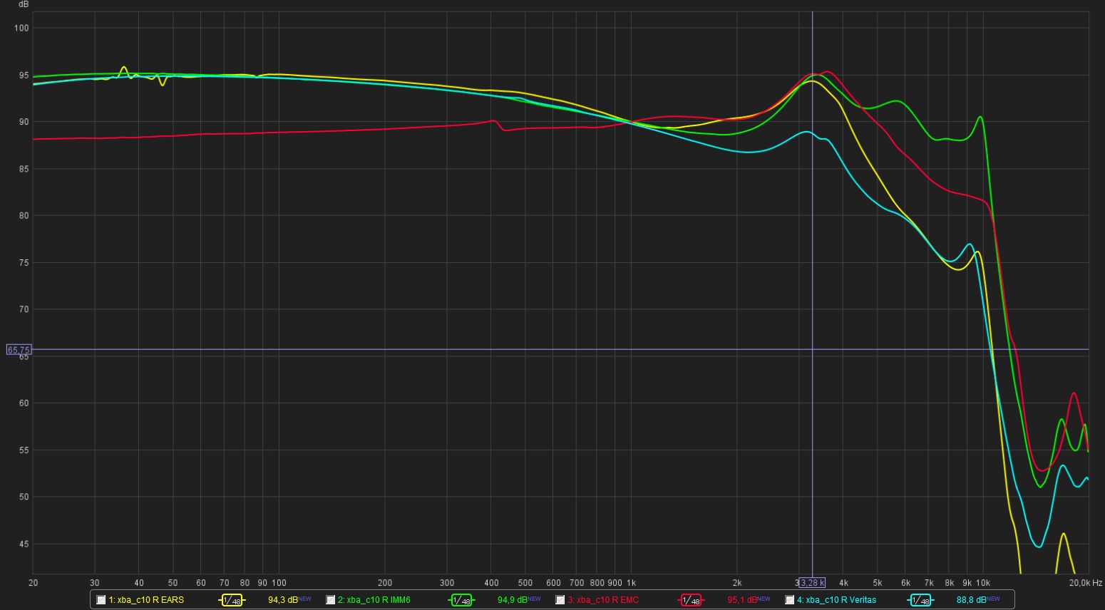
There's a lot of discussion about headphone measurements, and I think it's important, when looking at graphs/plots, to understand that there are many different headphone measurement systems and methods, and you're likely to get as much variation in measurements as there are different measurement rigs and people doing the measuring.
This is a topic I'll be discussing more and more in the coming months.
This is an oft-overlooked discussion, the comparison of headphone measurements made by different people with different setups. As catscratch said, it can make measurements made with different systems rather challenging to compare.
There are many different kinds of measurement setups. Some have gone the more homegrown route, like purrin (also known as Marvey) and Rin Choi (also known as udauda), both using DIY measurement setups.
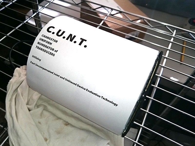
purrin (Marvey) has elected not to use a manikin, ear simulator, or pinna/canal assembly. I'm not sure that his measurement system was ever discussed in great detail. When asked about his measurement system on Head-Fi, purrin (Marvey) called his coupler "semi-secret." (link) During a discussion at the Newport Beach audio show last year, when asked which coupler he uses, Marvey responded (embedded video below): "I'm actually not using a dummy head. The reason is I actually did try a dummy head and there's some issues with that. With dummy heads you've got the ears, and the really good ones have got the tubes in them, and those create some specific resonances, that...don't necessarily represent what we hear. If I were to do a CSD measurement with one of those couplers, there would be all sorts of resonances that are inherent to the human auditory system which I feel that the brain filters out. So what I actually did was I built a custom coupler. Essentially, what it does...it tries to minimize the effects of the ear, the ear canal, while at the same time trying to be realistic of what we actually hear."
Here are photos of Marvey's custom coupler setup (click the images below to see them in full size):


2015-04-17 UPDATE: Marvey has updated his measurement rig with the following DIY fixture. Here are photos (click photos to see larger versions):


He has described its basic structure as foam, plastic plate with hole (using a CD), and Creatology foam with hole cut for microphone. Here is Marvey's description, in greater detail:
Rin Choi (who goes by udauda on Head-Fi) created his own dummy head that he named EURI (photos below). It is covered in a latex skin to "effectively simulate the damping effect of a human skin & insulate any acoustic leakage between the pinna simulators & the head itself." Inside of EURI can be found IEC 60318-4 occluded ear simulators (the manufacturer of his ear simulators was not specified). On his website, it seems to me that Rin is targeting industry standards (in terms of methods and gear), and, with his own measurements, compares his EURI head to commercial alternatives.
Here are photos of Rin's EURI head and the 60318-4 occluded ear simulator (click the images below to see them in full size):


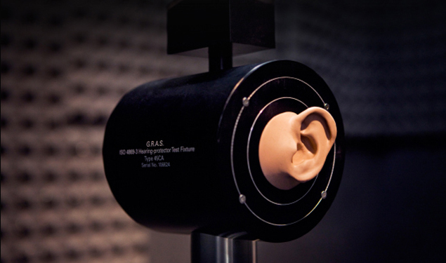
Looking at measurement setups that adhere more to industry standards than the aforementioned, Tyll Hertsens (Editor-In-Chief of Innerfidelity), as he describes here, uses a measurement head (the Head Acoustics HMS II.3). It is one of the industry standard measurement manikins. From that link above, you can read about Tyll's complete measurement system, including the acoustic isolation chamber he custom-built, the Audio Precision System 2 Cascade audio tester, and other components of his setup (and his methodology). Here are photos of his setup that he posted in that article (click the images below to see them in full size):


In one of the more recent headphone studies presented at AES by Sean Olive (Director Acoustic Research at Harman International and President-Elect at AES) and Todd Welti (Research Acoustician at Harman International), measurements were made using a GRAS 43AG Ear and Cheek Simulator equipped with an ITU-T type 3.3 pinna. (More specific details can be found in the full paper--Convention Paper 8744*--on the AES website.) Again, the GRAS piece and pinna is another industry standard measurement setup. Here are photos of the GRAS, both without and with a ear/cheek affixed (click the images below to see them in full size):


Keith Howard in Stereophile also mentions that he uses a GRAS ear and cheek simulator; Brent Butterworth of Sound And Vision also uses a GRAS device. 2017-11-16 UPDATE: Brent is now using GRAS's anthropometric pinnae on his 43AG.
In their AES Convention Paper 8994* (Listener Preferences for In-Room Loudspeaker and Headphone Target Responses), Sean Olive, Todd Welti, and Elisabeth McMullin used the GRAS 45CA. for their headphone measurements.
In AES Convention Paper 9118* (The Correlation Between Distortion Audibility and Listener Preference in Headphones), Steve Temme, Sean Olive, Steve Tatarunis, Todd Welti, and Elisabeth McMullin use the GRAS 45CA, as well as the Bruel & Kjaer Head and Torso simulator Type 4128.
Here are some photos of the GRAS 45CA:

(Photo from this page on rinchoi.blogspot.com.)


The GRAS 45CA is, in a way, like having two GRAS 43AG Ear and Cheek Simulators combined, so both channels of a stereo headphone can be measured at once. One key advantage of the 45CA (versus the 43AG, or even a pair of them) is that the 45CA's "head" housing has median adult human head height and width (with cheek angles), so headphone clamping force does not need to be measured separately and then dialed into the clamp. (The single-sided GRAS 43AG's clamp mechanism can also present some challenges with open-back earcups, because it clamps down on the center of the back of the headphone earcup.)
One key disadvantage of the 45CA versus the 43AG is that the 45CA is not nearly as portable. It is much larger, and much heavier than the 43AG.
I've been to several headphone manufacturer facilities, and have seen gear similar to the above-mentioned equipment in them (measurement manikins and fixtures, ear-and-cheek simulators, etc.).
2017-11-27 11:01 EST UPDATE: Head-Fi Audio Measurement Lab
Since we're talking about differences in measurements from others you've seen on the web, it's probably worthwhile to go over the current measurement systems we're using at Head-Fi's office. We've been putting together our measurement systems and techniques for nearly three years now, with a lot of help, knowledge, and feedback from industry mentors that include acoustical engineers and others who make their livings in/around audio measurements. There's always going to be much more learning ahead, no matter how much we do, how much we read, how much we're taught.
Anyway, here's what we're currently using at the office for audio measurements:
For headphone measurements, we're working with a head or fixture with more or less fixed dimensions (defined by international standards) representing average human dimensions, and those are the GRAS 45CA and the GRAS 45BB-12 KEMAR manikin.

In the photo (above), KEMAR is face-forward in our measurement lab, inside a custom Herzan acoustic/vibration isolation enclosure (more information below).
The pinnae / ear canals we use on the GRAS 45BB-12 KEMAR are anthropometric, based on 260 three-dimensional scans of human ear canals. These pinnae include the first bend and the second bend of the canals, with "flesh" all the way to the mics. Because they're more anatomically representative than traditional measurement pinnae, they have (among other features) a more realistic, more oval-shaped entrance point. Here's a photo of our current GRAS 45CA ears (which currently use standard measurement pinnae):

Here are a photo showing the new anthropometric pinna / canal:


Here's the same headphone on the new anthropometric pinnae on the GRAS 45BB-12 KEMAR:

Where in-ears are concerned, we've found the new pinnae/canals to help tremendously with more realistic and consistent placement, as the pinnae/canals are definitely more human-like now. With this improved realism we've found, for example, that characterizing the differences between eartip types via measurements (relative to our subjective experiences) is improved.
Additionally, I think the dimensional characteristics of the rig we're currently using (a GRAS KEMAR) might also contribute to some of the differences (especially versus the type of DIY rigs shown in the photos above). KEMAR has head shape characteristics that lead to more dimensional limitations on placement -- more human-like limitations, in my opinion. Whereas on a flat plate coupler you can place the headphone in any number of places and still maintain a seal (and thus maintain bass, the loss of which is one of the primary indicators that fit has gone wrong). On humans -- and on KEMAR -- if you go too far back, the curvature of our head can break the seal. Too far down on a human (and KEMAR) and you can also lose seal. In other words, the dimensional limitations of our anatomy -- and the larger the headphone, the more this may come into play -- play a role in guiding and limiting the placement range of the headphone over our ears in actual use. In the frequency ranges we're talking about (as the wavelengths get shorter), minor shifts in placement and dimensions can have substantial effects.
Unlike the DIY rigs shown in the photos that began this post, the measurement manikin (GRAS 45BB-12) and fixture (GRAS 45CA) use ear simulators to simulate the input and transfer impedance of a human ear. The GRAS 43BB ear simulators in this specific KEMAR configuration are quite different than standard 60318-4 simulators. While they still meet the IEC 60318-4 tolerances, the single high-Q resonance above 10 kHz is replaced by two more balanced, more damped resonances. The splitting of the one high-Q resonance into two low-Q resonances may present an advantage in decreasing the uncertainty in the measurements around the resonance (above 10 kHz). Also, the GRAS 43BB is highly sensitive, and very low-noise, and extends the lower dynamic range below the threshold of human hearing. Given its extremely low-noise nature, the 43BB can be used to measure and characterize things like the self-noise of an active headphone (both with and without active noise canceling), which is something we'll be increasingly interested in with the growing prominence of high-fidelity wireless headphones and earphones. It can also help in measuring low-level distortion in headphones and earphones. NOTE: One thing to consider with this low-noise simulator is that it's not suited to very-high-SPL measurements, with an upper limit of the dynamic range to about 110 dBSPL. This hasn't been an issue for us, though, as most of our measurements are set at 90 dBSPL (at 1 kHz).
Here's a whitepaper about the GRAS 43BB Low Noise Ear Simulator
A few weeks ago, GRAS announced still another ear simulator designed specifically for measuring high-resolution headphones. On Friday (two days ago) we took delivery of the new GRAS RA0401 High Resolution Ear Simulators, and we'll be installing them on our GRAS 45CA, along with the new anthropometric pinnae for the GRAS 45CA.


This is still another very exciting development for headphone measurements, as obtaining meaningful measurements above 8 kHz with most systems can be enormously challenging. This new GRAS RA0401 High Resolution Ear Simulator also meets the IEC 60318-4 tolerances, but GRAS was able to design it so that its performance from 10 kHz to 20 kHz is substantially improved, that range through which it has a tolerance of +/- 2.2 dB. Here is a graph showing the RA0401's response (including the IEC 60318-4 tolerances) compared to a standard 60318-4 ear simulator:

Again, meaningful headphone measurements above 8 kHz or 10 kHz have been a major pain point for decades, so I think these new GRAS High Resolution Ear Simulators may prove an important development in the world of headphone testing.
Here's a whitepaper about the GRAS High Resolution Ear Simulator
Unfortunately, we haven't had a chance to run our own measurements with the new RA0401 High Resolution Ear Simulators yet, as we shipped our measurement mic preamp power supply back to GRAS for a check-up and any necessary calibration (as it's now nearly three years old, and has been jostled around quite a bit). We should have that (GRAS 12AQ) back in the next few days, and we'll fire up these newest ear simulators just as soon as we do.
To help improve the quality of the measurements, we wanted to maximize environmental isolation. Though we obviously do not have the space (not to mention the budget) to build a full walk-in anechoic chamber, we still wanted to achieve as much acoustic and vibration isolation as reasonably possible. Skylar Gray (formerly of AudioQuest, now with Definitive Technology) recommended we contact Herzan. We worked with Herzan to carefully spec out a custom-built acoustic and vibration isolation enclosure. Our Herzan enclosure has thick walls, made with 11 variable density layers of sound-damping material, and the interior of the enclosure is lined with acoustic sound absorption foam. This enclosure is (by design) fairly massive, weighing around 1200 pounds -- the more mass there is, the more energy it takes to excite the system. The enclosure has two cable ports, both covered with solid machined metal screw-down blocks that are damped, and also have soft gaskets that allow full sealing around the cables. (See photo below.)
The headphone measurement manikin or fixture being used at the time is placed on a Herzan Onyx-6M vibration isolation table, to further help isolate the system from vibrations caused by foot traffic, HVAC systems, vehicle traffic, etc. The Onyx-6M is essentially a steel tabletop supported by pneumatic isolators, and provides isolation beginning at 4.5 Hz.

(Above) Closed left-side cable port on the Herzan acoustic/vibration isolation enclosure.
Even with the Herzan enclosure, we still make sure to keep it as quiet as we can in the office while doing measurements. Both of the office HVAC systems are switched off when we measure. You'll frequently hear the tongue-in-cheek cry, "Measurement in 3...2...1...fire in the hole!" before we start a measurement, and everyone remains quiet until an all-clear is given. We're particularly careful about this when using the GRAS 43BB ear simulators because, again, their dynamic range extends below the threshold of human hearing -- so even the very faintest sounds you can hear can be heard by the 43BB's.
The Audio Analyzer: Audio Precision APx555 and APx1701
At the center of our audio measurements -- whether we're doing electronic measurements (another topic for another time) or headphone measurements -- is an audio analyzer. The audio analyzer generates a stimulus of known characteristics, and then analyzes the response. (Wikipedia has an entry for "audio analyzer" which you can see at the following link for more general information about them: audio analyzer.)
We use the Audio Precision APx555 audio analyzer. In terms of its analog performance, the APx555 has a typical residual THD+N of -120 dB and over 1 MHz bandwidth, which exceeds the analog performance of all other audio analyzers. It will also do FFTs of 1.2 million points and full 24-bit resolution. The Audio Precision APx555 is an incredible tool, whether we're measuring DACs and amps (again, another topic, another time) or doing electro-acoustic tests, which is obviously more relevant to this thread's topic.
For some reading about the importance of low test system noise floor, Dan Foley from Audio Precision (one of my audio measurement mentors for over two years) wrote an article for audioXpress titled "Test and Measurement: 'I Can Hear It. Why Can't I Measure It?'" In this article, Dan uses headphones as a key example, as he discusses the human hearing threshold and how it relates to the noise floor of a sound card interface compared to an audio analyzer's noise floor. You can read this article at the following link:
"Test and Measurement: 'I Can Hear It. Why Can't I Measure It?'"
We've also added all of Audio Precision's Electro-Acoustic Test Options to the APx555 through their Electro-Acoustic Research & Development option (APX-SW-SPK-RD), which is a suite of measurements intended for designers and engineers who develop electro-acoustic audio products. You'll be seeing some measurements specific to this module from us in the near future, along with explanations of them.
Earlier I mentioned testing wireless headphones. Another update we're making to our measurement lab very soon is the addition of Audio Precision's new Bluetooth Duo Module to the Audio Precision APx555 audio analyzer. This new Bluetooth module can act as source and sink for AAC, aptX, aptX-HD, aptX-LL, and SBC. Yes, I said aptX-HD, and yes I'm very excited about that. Last year we had two aptX-HD-enabled wireless headphones in our office. Now we have many more, and it will be exciting to be able to measure these headphones at their wireless best. We'll be covering this module more over time.

In the photo above, the Audio Precision APx555 Audio Analyzer (bottom) and Audio Precision APx1701 Transducer Test Interface.
For amplification (to drive the earphones and headphones), we use the Audio Precision APx1701 Transducer Test Interface. The APx1701 integrates instrument-grade amplifiers and microphone power supplies, but we do not currently use its mic power supplies (we use GRAS's power modules). The APx1701 is made to drive both loudspeakers and headphones, includes current-sense resistors in the amplifier outputs for impedance measurements, has a signal-to-noise ratio of 134 dB, THD+N is ≤ -105 dB, output impedance is 0.13Ω, and it can drive up to 100W per channel into 8Ω. Given the APx1701's fixed gain of 20 dB, we will sometimes use the Rupert Neve Designs RNHP headphone amplifier (set to unity gain) to drive more sensitive headphones and earphones.
Keeping all of the measurement equipment calibrated and maintained is obviously important. We do the calibrations we can do at the office. We use GRAS pistonphones to regularly calibrate the measurement microphones and systems. Ideally, we would do this before every measurement session -- we do it no more than once per month, corrected for temperature and ambient static pressure at the time of the calibration. We run Audio Precision's APx Self Test utility on the APx555 from time to time to confirm proper operation of its analog and digital sections. (We have not yet run that utility on the APx1701, which is still quite new.) We do occasionally measure the Neve RNHP on the APx555 just to confirm the consistency of its performance and to confirm unity gain. We intend to adhere to the manufacturers' maintenance and calibration schedules, and will send the gear to them for check up and calibration accordingly.
We're in the process of shooting Head-Fi TV videos now to discuss the components of the measurement systems in Head-Fi's audio measurement lab, including some examples of them in actual use.
Again, the measurement setups and methodologies can differ substantially from measurer to measurer. Some use more industry standard equipment and methodologies; still others claim to sidestep industry standards for individual reasons and/or claims of more accurate measurement results. So, as was stated earlier, it can be tough to make meaningful comparisons of measurements between the results of the different providers of them.
* The direct-download links for the AES papers require AES membership with AES E-Library paid access.
2015-04-17 1211 EDT: Updated with v2 of purrin's measurement rig.
2015-04-24 0910 EDT: Updated with GRAS. 45CA.
2017-11-16 1347 EST: Updated information about Brent Butterworth's measurement system.
2017-11-27 1101 EST: Updated post with information on the current Head-Fi audio measurement lab
There's a lot of discussion about headphone measurements, and I think it's important, when looking at graphs/plots, to understand that there are many different headphone measurement systems and methods, and you're likely to get as much variation in measurements as there are different measurement rigs and people doing the measuring.
This is a topic I'll be discussing more and more in the coming months.
You can't expect to derive anything out of comparing FR of two headphones from two separate measurement archives (different equipment/compensations)...
Purrin and Tyll use totally different measurement techniques and apply totally different compensation curves. It is absolutely pointless to cross-compare them...
This is an oft-overlooked discussion, the comparison of headphone measurements made by different people with different setups. As catscratch said, it can make measurements made with different systems rather challenging to compare.
There are many different kinds of measurement setups. Some have gone the more homegrown route, like purrin (also known as Marvey) and Rin Choi (also known as udauda), both using DIY measurement setups.
purrin (Marvey) has elected not to use a manikin, ear simulator, or pinna/canal assembly. I'm not sure that his measurement system was ever discussed in great detail. When asked about his measurement system on Head-Fi, purrin (Marvey) called his coupler "semi-secret." (link) During a discussion at the Newport Beach audio show last year, when asked which coupler he uses, Marvey responded (embedded video below): "I'm actually not using a dummy head. The reason is I actually did try a dummy head and there's some issues with that. With dummy heads you've got the ears, and the really good ones have got the tubes in them, and those create some specific resonances, that...don't necessarily represent what we hear. If I were to do a CSD measurement with one of those couplers, there would be all sorts of resonances that are inherent to the human auditory system which I feel that the brain filters out. So what I actually did was I built a custom coupler. Essentially, what it does...it tries to minimize the effects of the ear, the ear canal, while at the same time trying to be realistic of what we actually hear."
Here are photos of Marvey's custom coupler setup (click the images below to see them in full size):
2015-04-17 UPDATE: Marvey has updated his measurement rig with the following DIY fixture. Here are photos (click photos to see larger versions):
He has described its basic structure as foam, plastic plate with hole (using a CD), and Creatology foam with hole cut for microphone. Here is Marvey's description, in greater detail:
Originally Posted by Marvey
I filled the inside with medium density open cell foam - to simulate brains. Use something squishy to avoid interactions between L and R.
- In the middle of the foam later, a piece of felt about the size of an ear. Without this piece, I found measurements too ringy. Covered completely with felt, I found measurements too damped. The felt the size of an ear also serves another function. Proper measurement of supra-aurals that rest of the ear.
- I use a strip of felt to simulate hair and sometimes another strip to simulate imperfect seal of the nape of the neck. Knowing to get a properly simulated seal is crucial.
- The hard plastic plate (use a CD) is a good bone simulator.
Really, you could just put the felt / foam layer on top of a CD on top of a foam brick. I just made it look nicer and named it C.U.N.T. to establish "cred". We all know that stuff that looks nice, that is shiny white, and has a euro kind of acronym like G.R.A.S. or C.U.N.T. must be good.
Rin Choi (who goes by udauda on Head-Fi) created his own dummy head that he named EURI (photos below). It is covered in a latex skin to "effectively simulate the damping effect of a human skin & insulate any acoustic leakage between the pinna simulators & the head itself." Inside of EURI can be found IEC 60318-4 occluded ear simulators (the manufacturer of his ear simulators was not specified). On his website, it seems to me that Rin is targeting industry standards (in terms of methods and gear), and, with his own measurements, compares his EURI head to commercial alternatives.
Here are photos of Rin's EURI head and the 60318-4 occluded ear simulator (click the images below to see them in full size):
Looking at measurement setups that adhere more to industry standards than the aforementioned, Tyll Hertsens (Editor-In-Chief of Innerfidelity), as he describes here, uses a measurement head (the Head Acoustics HMS II.3). It is one of the industry standard measurement manikins. From that link above, you can read about Tyll's complete measurement system, including the acoustic isolation chamber he custom-built, the Audio Precision System 2 Cascade audio tester, and other components of his setup (and his methodology). Here are photos of his setup that he posted in that article (click the images below to see them in full size):
In one of the more recent headphone studies presented at AES by Sean Olive (Director Acoustic Research at Harman International and President-Elect at AES) and Todd Welti (Research Acoustician at Harman International), measurements were made using a GRAS 43AG Ear and Cheek Simulator equipped with an ITU-T type 3.3 pinna. (More specific details can be found in the full paper--Convention Paper 8744*--on the AES website.) Again, the GRAS piece and pinna is another industry standard measurement setup. Here are photos of the GRAS, both without and with a ear/cheek affixed (click the images below to see them in full size):
Keith Howard in Stereophile also mentions that he uses a GRAS ear and cheek simulator; Brent Butterworth of Sound And Vision also uses a GRAS device. 2017-11-16 UPDATE: Brent is now using GRAS's anthropometric pinnae on his 43AG.
In their AES Convention Paper 8994* (Listener Preferences for In-Room Loudspeaker and Headphone Target Responses), Sean Olive, Todd Welti, and Elisabeth McMullin used the GRAS 45CA. for their headphone measurements.
In AES Convention Paper 9118* (The Correlation Between Distortion Audibility and Listener Preference in Headphones), Steve Temme, Sean Olive, Steve Tatarunis, Todd Welti, and Elisabeth McMullin use the GRAS 45CA, as well as the Bruel & Kjaer Head and Torso simulator Type 4128.
Here are some photos of the GRAS 45CA:
(Photo from this page on rinchoi.blogspot.com.)
The GRAS 45CA is, in a way, like having two GRAS 43AG Ear and Cheek Simulators combined, so both channels of a stereo headphone can be measured at once. One key advantage of the 45CA (versus the 43AG, or even a pair of them) is that the 45CA's "head" housing has median adult human head height and width (with cheek angles), so headphone clamping force does not need to be measured separately and then dialed into the clamp. (The single-sided GRAS 43AG's clamp mechanism can also present some challenges with open-back earcups, because it clamps down on the center of the back of the headphone earcup.)
One key disadvantage of the 45CA versus the 43AG is that the 45CA is not nearly as portable. It is much larger, and much heavier than the 43AG.
I've been to several headphone manufacturer facilities, and have seen gear similar to the above-mentioned equipment in them (measurement manikins and fixtures, ear-and-cheek simulators, etc.).
2017-11-27 11:01 EST UPDATE: Head-Fi Audio Measurement Lab
Since we're talking about differences in measurements from others you've seen on the web, it's probably worthwhile to go over the current measurement systems we're using at Head-Fi's office. We've been putting together our measurement systems and techniques for nearly three years now, with a lot of help, knowledge, and feedback from industry mentors that include acoustical engineers and others who make their livings in/around audio measurements. There's always going to be much more learning ahead, no matter how much we do, how much we read, how much we're taught.
Anyway, here's what we're currently using at the office for audio measurements:
GRAS KEMAR, 45CA, Ear Simulators, and Pinnae / Canals
For headphone measurements, we're working with a head or fixture with more or less fixed dimensions (defined by international standards) representing average human dimensions, and those are the GRAS 45CA and the GRAS 45BB-12 KEMAR manikin.
In the photo (above), KEMAR is face-forward in our measurement lab, inside a custom Herzan acoustic/vibration isolation enclosure (more information below).
The pinnae / ear canals we use on the GRAS 45BB-12 KEMAR are anthropometric, based on 260 three-dimensional scans of human ear canals. These pinnae include the first bend and the second bend of the canals, with "flesh" all the way to the mics. Because they're more anatomically representative than traditional measurement pinnae, they have (among other features) a more realistic, more oval-shaped entrance point. Here's a photo of our current GRAS 45CA ears (which currently use standard measurement pinnae):
Another advantage of the new pinnae is their increased realism externally. If you've ever felt measurement pinnae, they're typically stiffer than human pinnae and don't readily compress against the head, which is why many who measure headphones often have difficulty measuring supra-aural (on-the-ear) headphones with them. (They can also present problems with measuring shallow-cup circumaurals.) The new pinnae feel and move much more like human pinnae and compress against the head much more like (most) people's pinnae do. Here is a photo I took of the supra-aural Audeze Sine on the standard measurement pinnae on a GRAS 45CA:Here's the same headphone on the new anthropometric pinnae on the GRAS 45BB-12 KEMAR:
Where in-ears are concerned, we've found the new pinnae/canals to help tremendously with more realistic and consistent placement, as the pinnae/canals are definitely more human-like now. With this improved realism we've found, for example, that characterizing the differences between eartip types via measurements (relative to our subjective experiences) is improved.
Additionally, I think the dimensional characteristics of the rig we're currently using (a GRAS KEMAR) might also contribute to some of the differences (especially versus the type of DIY rigs shown in the photos above). KEMAR has head shape characteristics that lead to more dimensional limitations on placement -- more human-like limitations, in my opinion. Whereas on a flat plate coupler you can place the headphone in any number of places and still maintain a seal (and thus maintain bass, the loss of which is one of the primary indicators that fit has gone wrong). On humans -- and on KEMAR -- if you go too far back, the curvature of our head can break the seal. Too far down on a human (and KEMAR) and you can also lose seal. In other words, the dimensional limitations of our anatomy -- and the larger the headphone, the more this may come into play -- play a role in guiding and limiting the placement range of the headphone over our ears in actual use. In the frequency ranges we're talking about (as the wavelengths get shorter), minor shifts in placement and dimensions can have substantial effects.
Unlike the DIY rigs shown in the photos that began this post, the measurement manikin (GRAS 45BB-12) and fixture (GRAS 45CA) use ear simulators to simulate the input and transfer impedance of a human ear. The GRAS 43BB ear simulators in this specific KEMAR configuration are quite different than standard 60318-4 simulators. While they still meet the IEC 60318-4 tolerances, the single high-Q resonance above 10 kHz is replaced by two more balanced, more damped resonances. The splitting of the one high-Q resonance into two low-Q resonances may present an advantage in decreasing the uncertainty in the measurements around the resonance (above 10 kHz). Also, the GRAS 43BB is highly sensitive, and very low-noise, and extends the lower dynamic range below the threshold of human hearing. Given its extremely low-noise nature, the 43BB can be used to measure and characterize things like the self-noise of an active headphone (both with and without active noise canceling), which is something we'll be increasingly interested in with the growing prominence of high-fidelity wireless headphones and earphones. It can also help in measuring low-level distortion in headphones and earphones. NOTE: One thing to consider with this low-noise simulator is that it's not suited to very-high-SPL measurements, with an upper limit of the dynamic range to about 110 dBSPL. This hasn't been an issue for us, though, as most of our measurements are set at 90 dBSPL (at 1 kHz).
Here's a whitepaper about the GRAS 43BB Low Noise Ear Simulator
A few weeks ago, GRAS announced still another ear simulator designed specifically for measuring high-resolution headphones. On Friday (two days ago) we took delivery of the new GRAS RA0401 High Resolution Ear Simulators, and we'll be installing them on our GRAS 45CA, along with the new anthropometric pinnae for the GRAS 45CA.
This is still another very exciting development for headphone measurements, as obtaining meaningful measurements above 8 kHz with most systems can be enormously challenging. This new GRAS RA0401 High Resolution Ear Simulator also meets the IEC 60318-4 tolerances, but GRAS was able to design it so that its performance from 10 kHz to 20 kHz is substantially improved, that range through which it has a tolerance of +/- 2.2 dB. Here is a graph showing the RA0401's response (including the IEC 60318-4 tolerances) compared to a standard 60318-4 ear simulator:
Again, meaningful headphone measurements above 8 kHz or 10 kHz have been a major pain point for decades, so I think these new GRAS High Resolution Ear Simulators may prove an important development in the world of headphone testing.
Here's a whitepaper about the GRAS High Resolution Ear Simulator
Unfortunately, we haven't had a chance to run our own measurements with the new RA0401 High Resolution Ear Simulators yet, as we shipped our measurement mic preamp power supply back to GRAS for a check-up and any necessary calibration (as it's now nearly three years old, and has been jostled around quite a bit). We should have that (GRAS 12AQ) back in the next few days, and we'll fire up these newest ear simulators just as soon as we do.
To help improve the quality of the measurements, we wanted to maximize environmental isolation. Though we obviously do not have the space (not to mention the budget) to build a full walk-in anechoic chamber, we still wanted to achieve as much acoustic and vibration isolation as reasonably possible. Skylar Gray (formerly of AudioQuest, now with Definitive Technology) recommended we contact Herzan. We worked with Herzan to carefully spec out a custom-built acoustic and vibration isolation enclosure. Our Herzan enclosure has thick walls, made with 11 variable density layers of sound-damping material, and the interior of the enclosure is lined with acoustic sound absorption foam. This enclosure is (by design) fairly massive, weighing around 1200 pounds -- the more mass there is, the more energy it takes to excite the system. The enclosure has two cable ports, both covered with solid machined metal screw-down blocks that are damped, and also have soft gaskets that allow full sealing around the cables. (See photo below.)
The headphone measurement manikin or fixture being used at the time is placed on a Herzan Onyx-6M vibration isolation table, to further help isolate the system from vibrations caused by foot traffic, HVAC systems, vehicle traffic, etc. The Onyx-6M is essentially a steel tabletop supported by pneumatic isolators, and provides isolation beginning at 4.5 Hz.
(Above) Closed left-side cable port on the Herzan acoustic/vibration isolation enclosure.
Even with the Herzan enclosure, we still make sure to keep it as quiet as we can in the office while doing measurements. Both of the office HVAC systems are switched off when we measure. You'll frequently hear the tongue-in-cheek cry, "Measurement in 3...2...1...fire in the hole!" before we start a measurement, and everyone remains quiet until an all-clear is given. We're particularly careful about this when using the GRAS 43BB ear simulators because, again, their dynamic range extends below the threshold of human hearing -- so even the very faintest sounds you can hear can be heard by the 43BB's.
The Audio Analyzer: Audio Precision APx555 and APx1701
At the center of our audio measurements -- whether we're doing electronic measurements (another topic for another time) or headphone measurements -- is an audio analyzer. The audio analyzer generates a stimulus of known characteristics, and then analyzes the response. (Wikipedia has an entry for "audio analyzer" which you can see at the following link for more general information about them: audio analyzer.)
We use the Audio Precision APx555 audio analyzer. In terms of its analog performance, the APx555 has a typical residual THD+N of -120 dB and over 1 MHz bandwidth, which exceeds the analog performance of all other audio analyzers. It will also do FFTs of 1.2 million points and full 24-bit resolution. The Audio Precision APx555 is an incredible tool, whether we're measuring DACs and amps (again, another topic, another time) or doing electro-acoustic tests, which is obviously more relevant to this thread's topic.
For some reading about the importance of low test system noise floor, Dan Foley from Audio Precision (one of my audio measurement mentors for over two years) wrote an article for audioXpress titled "Test and Measurement: 'I Can Hear It. Why Can't I Measure It?'" In this article, Dan uses headphones as a key example, as he discusses the human hearing threshold and how it relates to the noise floor of a sound card interface compared to an audio analyzer's noise floor. You can read this article at the following link:
"Test and Measurement: 'I Can Hear It. Why Can't I Measure It?'"
We've also added all of Audio Precision's Electro-Acoustic Test Options to the APx555 through their Electro-Acoustic Research & Development option (APX-SW-SPK-RD), which is a suite of measurements intended for designers and engineers who develop electro-acoustic audio products. You'll be seeing some measurements specific to this module from us in the near future, along with explanations of them.
Earlier I mentioned testing wireless headphones. Another update we're making to our measurement lab very soon is the addition of Audio Precision's new Bluetooth Duo Module to the Audio Precision APx555 audio analyzer. This new Bluetooth module can act as source and sink for AAC, aptX, aptX-HD, aptX-LL, and SBC. Yes, I said aptX-HD, and yes I'm very excited about that. Last year we had two aptX-HD-enabled wireless headphones in our office. Now we have many more, and it will be exciting to be able to measure these headphones at their wireless best. We'll be covering this module more over time.
In the photo above, the Audio Precision APx555 Audio Analyzer (bottom) and Audio Precision APx1701 Transducer Test Interface.
For amplification (to drive the earphones and headphones), we use the Audio Precision APx1701 Transducer Test Interface. The APx1701 integrates instrument-grade amplifiers and microphone power supplies, but we do not currently use its mic power supplies (we use GRAS's power modules). The APx1701 is made to drive both loudspeakers and headphones, includes current-sense resistors in the amplifier outputs for impedance measurements, has a signal-to-noise ratio of 134 dB, THD+N is ≤ -105 dB, output impedance is 0.13Ω, and it can drive up to 100W per channel into 8Ω. Given the APx1701's fixed gain of 20 dB, we will sometimes use the Rupert Neve Designs RNHP headphone amplifier (set to unity gain) to drive more sensitive headphones and earphones.
Keeping all of the measurement equipment calibrated and maintained is obviously important. We do the calibrations we can do at the office. We use GRAS pistonphones to regularly calibrate the measurement microphones and systems. Ideally, we would do this before every measurement session -- we do it no more than once per month, corrected for temperature and ambient static pressure at the time of the calibration. We run Audio Precision's APx Self Test utility on the APx555 from time to time to confirm proper operation of its analog and digital sections. (We have not yet run that utility on the APx1701, which is still quite new.) We do occasionally measure the Neve RNHP on the APx555 just to confirm the consistency of its performance and to confirm unity gain. We intend to adhere to the manufacturers' maintenance and calibration schedules, and will send the gear to them for check up and calibration accordingly.
We're in the process of shooting Head-Fi TV videos now to discuss the components of the measurement systems in Head-Fi's audio measurement lab, including some examples of them in actual use.
Again, the measurement setups and methodologies can differ substantially from measurer to measurer. Some use more industry standard equipment and methodologies; still others claim to sidestep industry standards for individual reasons and/or claims of more accurate measurement results. So, as was stated earlier, it can be tough to make meaningful comparisons of measurements between the results of the different providers of them.
* The direct-download links for the AES papers require AES membership with AES E-Library paid access.
2015-04-17 1211 EDT: Updated with v2 of purrin's measurement rig.
2015-04-24 0910 EDT: Updated with GRAS. 45CA.
2017-11-16 1347 EST: Updated information about Brent Butterworth's measurement system.
2017-11-27 1101 EST: Updated post with information on the current Head-Fi audio measurement lab
Last edited:


