dcheming
100+ Head-Fier
- Joined
- Aug 2, 2005
- Posts
- 452
- Likes
- 13
Well I figured it was about time to condense all the info on modifying this amp into a dedicated thread. If you're interested to see where the majority of this info came from please see the main Xiang Sheng thread: http://www.head-fi.org/forums/f5/xia...be-amp-189198/
Intro
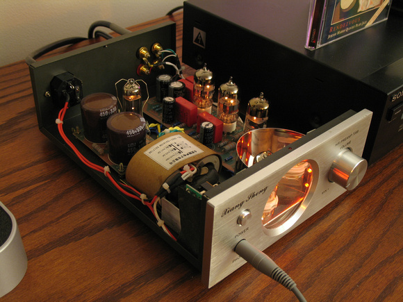
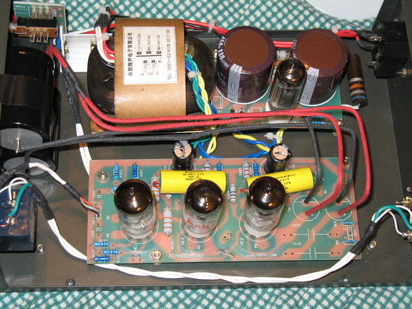
While the overall build quality of this amplifier isn't that bad, the quality of most of the parts is pretty low, but that's exactly why there is so much room for sonic improvement by doing modifications. One of the great things about this amp is that there is quite a bit of room inside, unlike most of the other tube amp offerings in this price range, and this makes it quite easy to add big parts such as film caps, electrolytic caps, and volume pots.
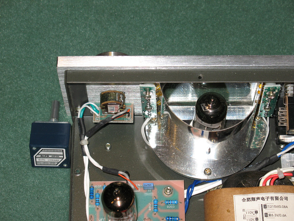
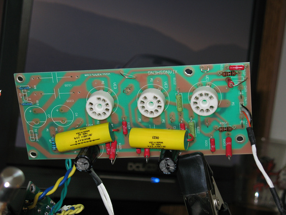
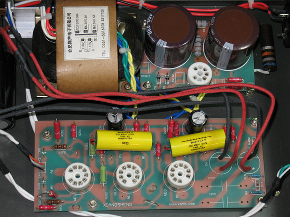
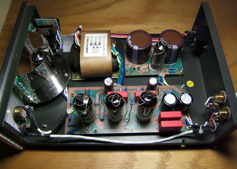
So to start off here's an inside pic of a bone stock 708B courtesy of Nugget:
Here's the schematic for the audio section courtesy of zer061zer0:

Here's the parts list:
Capacitors
C1,2 330uF 450V electrolytic - Main filter.
C6,7 150uF 200V electrolytic - Headphone output.
C8,9 33uF 450V electrolytic - Main filter bypass.
C101,201 0.1uF 50V film - Input.
C104,204 0.22uF 400V film - Interstage coupling.
C105,205 0.22uF 400V film - Preamp output.
Resistors
R101,201 1M 1/2W
R102,202 33K 2W - Anode load for 6N3.
R103,203 1K 1W - Cathode bias for 6N3.
R104,204 200R 1/2W
R105,205 220R 1W - Cathode bias for 6922.
R106,206 1M 1/2W
R107,207 1k 1w - Input.
R1 1K 2W
R2 2K 2W
R3,4 100R 1W
R7,8 100R 1W
R9,10 330K 1/4W - The value was hard to read so I'm not 100% positive on this one.
R1,2 10R 1W - Headphone output.
Misc
Vol Pot - 100K stereo audio/log taper
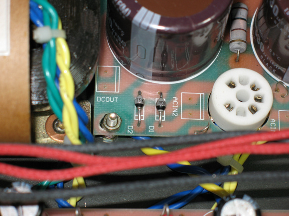
D1,2 1N4007 1A 1000V diodes
Screws - M3 x 0.5mm
Safety
Before I get into the main mods, I would like to touch upon a few things concerning safety while working on this amp. First and foremost is the fairly HV (~220VDC) that is present while the amp is powered up. If you are ever taking measurements in the circuit with your DMM while the power is on, it is recommended to keep one of your hands behind your back. Doing this eliminates the possibility of your body forming a path for HV to travel through, which could be fatal. It's a good habit to get into while measuring tube amps or anything electrical for that matter.
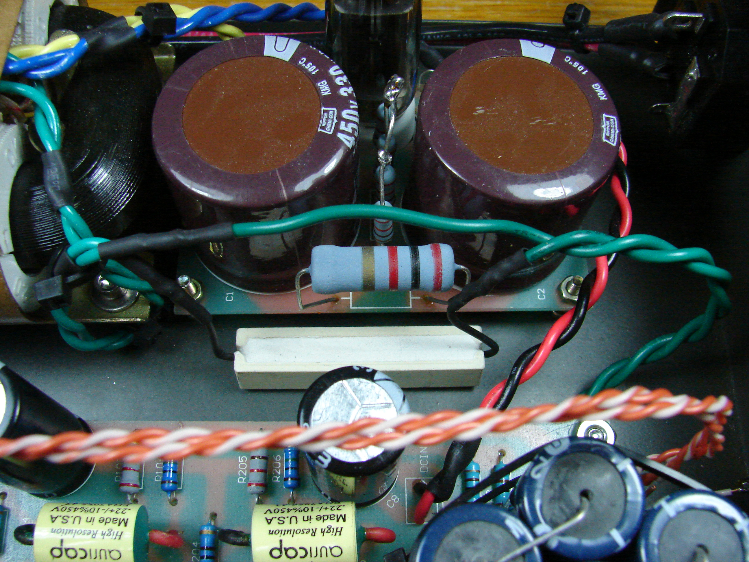
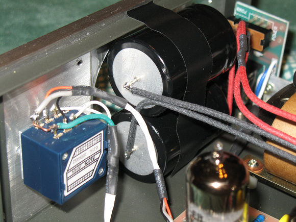
The other main thing to keep in mind is that the big 330uF filter capacitors in the power supply will remain charged for quite a while. So even if you unplug the amp there is still a considerable shock hazard with these big caps. Many amps employ bleeder resistors on the filter caps to safely drain them as soon as the power is tuned off. Unfortunately the XS 708B doesn't have these, so I'd highly recommend adding these as your first mod, especially if you plan on taking this amp apart a lot to do extensive mods. Anything from about 50KΩ to 200KΩ will be okay for this purpose. I soldered a 2W resistor to both of the caps to divide the heat to be dissipated into two resistors. If you used a 100KΩ resistor on each cap, then they will dissipate about 1/2 watt each. If you used a 150KΩ resistor on each cap, then they will dissipate about 1/3 watt each. Adding these resistors will drain the filter caps within a few minutes of the power being turned off. In the mean time you could just use something like a 25KΩ resistor with a pair of alligator clip wires to manually drain these caps.
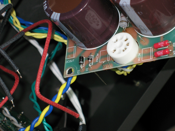
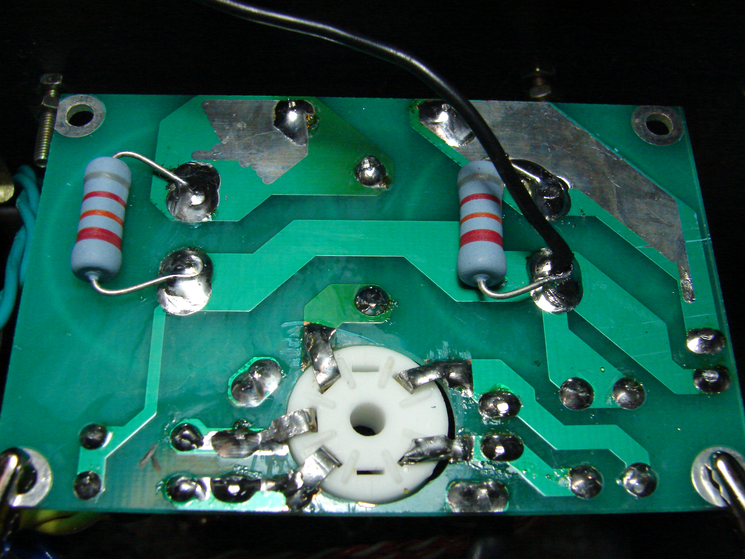
Bleeder resistors added:
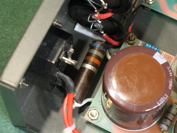
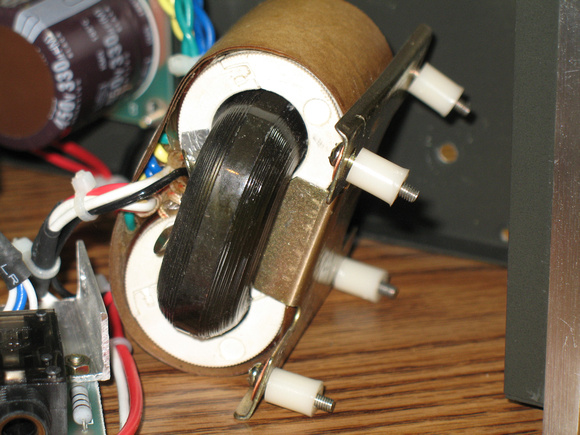
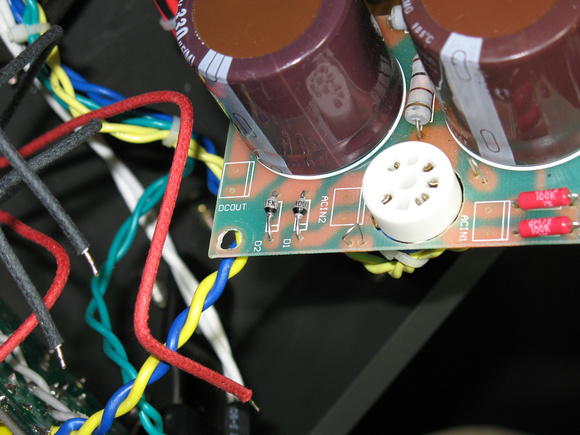
Another simple power supply mod that I recommend is replacing R1 and R2 in the power supply with higher wattage resistors. This isn't really necessary, but in my amp these two resistors were getting pretty hot. For R2 (2KΩ) I used a 3W NTE with plenty of space around it for good air circulation. R1 (1KΩ) is situated in between the two filter caps so I wanted to do something different here since the larger size of a 3W would bring it pretty close to the caps themselves, which could potentially heat them up. So for this I crafted an equivalent 1KΩ 4W resistor using four 1KΩ 1W resistors in series/parallel. This is ideal here since it gives plenty of power handling, good clearance in between the caps, and much better air circulation.

1KΩ 4W combo resistor:

Crucial Mods
The mods in this group are the ones that I feel make the biggest improvement in the sound. If you want to know what will give the biggest bang for the buck, this is where to start. This crucial group includes the volume pot, the input resistors, the interstage coupling caps, the output caps, and the output resistors.
Volume Pot
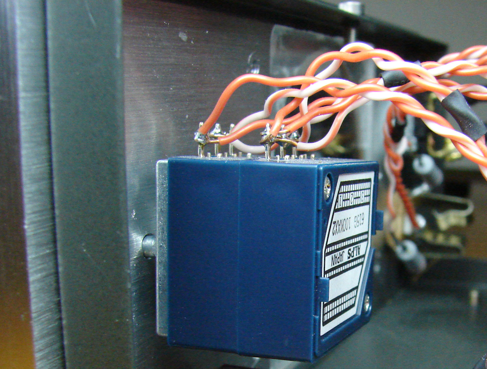
The stock volume pot is a very cheap carbon type and it suffers from pretty severe channel imbalance. This is especially a problem in the 7 to 8 o'clock range, which is right in the range where you'll be the majority of the time due to the very high gain of the 708B. I measured how much difference there was between the two channels for this pot at a few different rotations and it averaged about 2000Ω, which is why it has such horrible channel balance. I upgraded this to a 100KΩ ALPS stereo pot and I was very surprised by how much this helped with the clarity. The size of the soundstage increased a bit as well, which was especially noticeable with instruments that are panned far to one side.
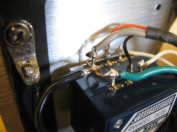
There's a few notes about doing this mod. The threaded barrel of the ALPS is slightly larger than the stock pot so you will have to enlarge the mounting hole a little bit. I did this by hand so I don't know what size drill bit is required. A new hole will also have to be drilled to locate the little tab on the ALPS that keeps it from rotating and I would recommend locating this hole to orient the pot with the pins facing up since this gives good access to them for later when upgrading the signal wire. The knob that I used is from Rat-Shack and since it's made for a 1/4" shaft I had to wrap a single layer of electrical tape around the shaft of the ALPS 6mm shaft for the knob to be centered. This particular knob almost fits into the circular recess milled into the faceplate and with a little bit of sanding to the knob's outer edge it'll fit inside.
Detail of new hole for tab and tape wrap:

Input & Output Resistors
Both pairs of these resistors are directly in the audio path and since low quality film resistors have the potential to be noisy I'd definitely change these four resistors. This is a very simple mod and there is a wide choice of options for these. You could just play it safe and use some nice metal films like PRP or Vishay/Dale, you could try something different like some RIKEN carbon films, or you could get crazy and go with some Audio Note tantalum film resistors here like some of us have. The input resistors are 1KΩ 1/2W (R107,207) and the headphone output resistors are 10Ω 2W (R1,2 *note that these two resistors share the same part number as the two resistors previously mentioned in the power supply so be careful).
RIKEN input resistors:

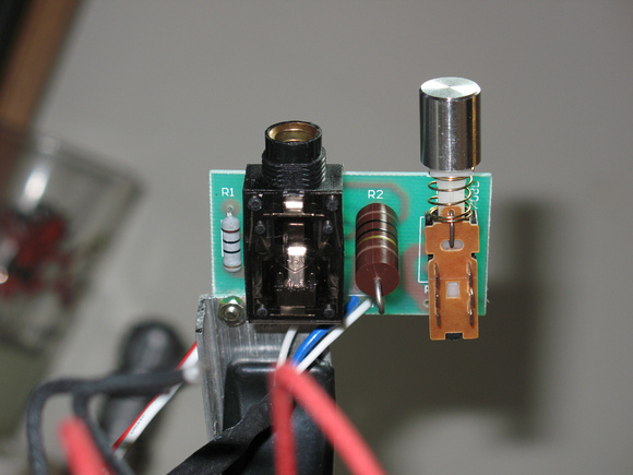
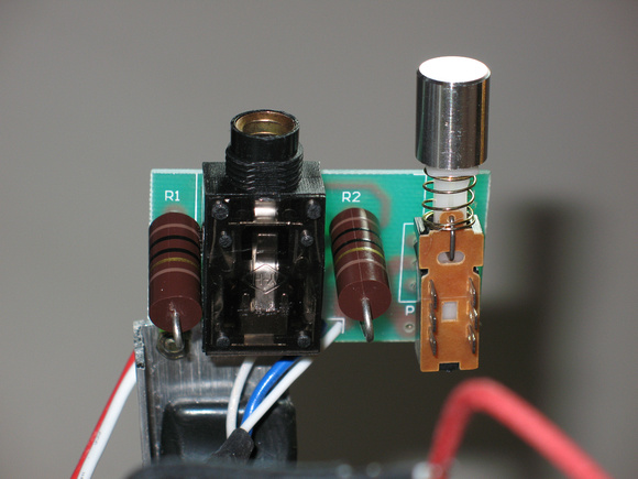
NTE output resistors on HP jack PCB:

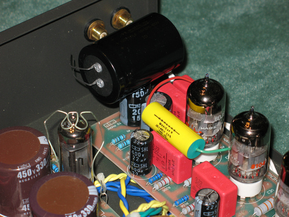
Interstage Coupling Caps
The stock caps here are WIMA metallized mylar so there is definitely room for improvement. Changing these caps (C104,204) has a pretty big affect on the sound, right up there with the changing the volume pot. I went with Auricaps for these, but I would recommend the Mundorf M-Cap ZN as a better choice for around the same price. Like the input/output resistors this is a very easy mod. For those who also plan on using the preamp output of the 708B I would upgrade C105,205 as well.

Headphone Output Caps
The stock ones are just some cheap 150uF electrolytic caps and needless to say these can be significantly improved upon. If you are using lower impedance cans I would increase their uF value, which lowers the frequency at which the bass rolls off. Since I use 300Ω cans I just went with 200uF here in the form of two ELNA 100uf 250V caps paralleled per channel. Whatever you end up using just make sure it's rated for at least 250V to be safe and make sure you observe polarity when installing these.


Other Signal-Path Mods
This is all the other stuff in the signal path that could be upgraded after the crucial mods above. This includes the RCA jacks, signal wire, jumper, input caps, and HP jack. Upgrading these still helps, just not nearly as much as the above group.
RCA Jacks
The RCA jacks in my amp were of very low quality and one was undersized enough to let the IC easily fall off. The solder job on these was also horrible. I replaced these with some Teflon Calrad RCA jacks. The mounting holes are 3/8" so any standard RCA jack will work.
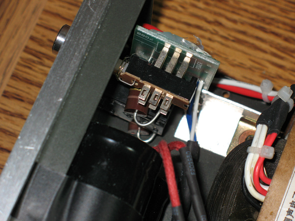
Stock jacks:

Calrad jacks:

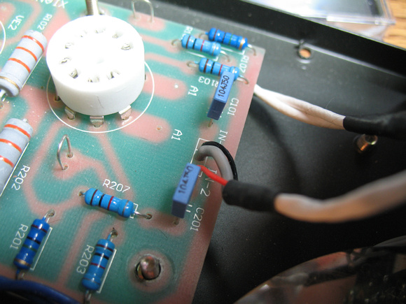
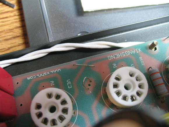
Signal Wire
The signal wire used in this amp is of fairly low quality as is the solder job on them. I used some Belden 7882A CAT6 Teflon wire to replace this since it's easy to work with and very affordable. Even though the stock wire is shielded I haven't had the slightest problem with hum by using this wire. Of course there are many options for wire here, but I would use something smaller than 20ga to avoid having to enlarge the holes in the PCB with a small drill bit.
Stock vs. Belden CAT6 wire:

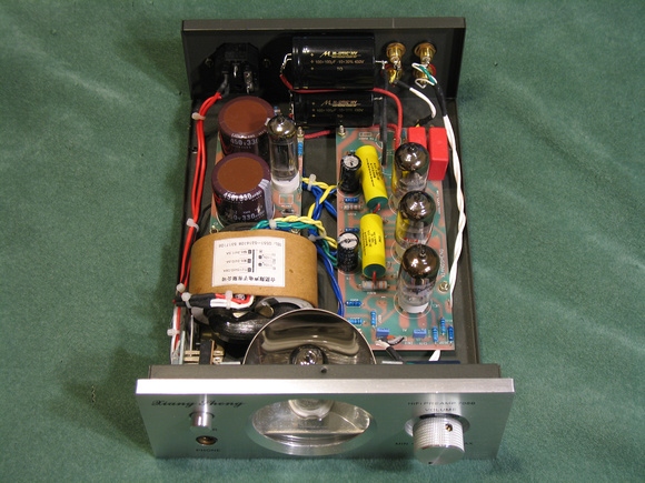
Amp with Belden CAT6 wire throughout:

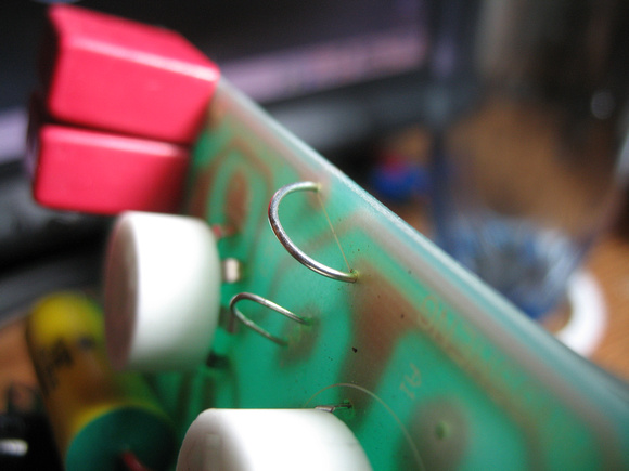
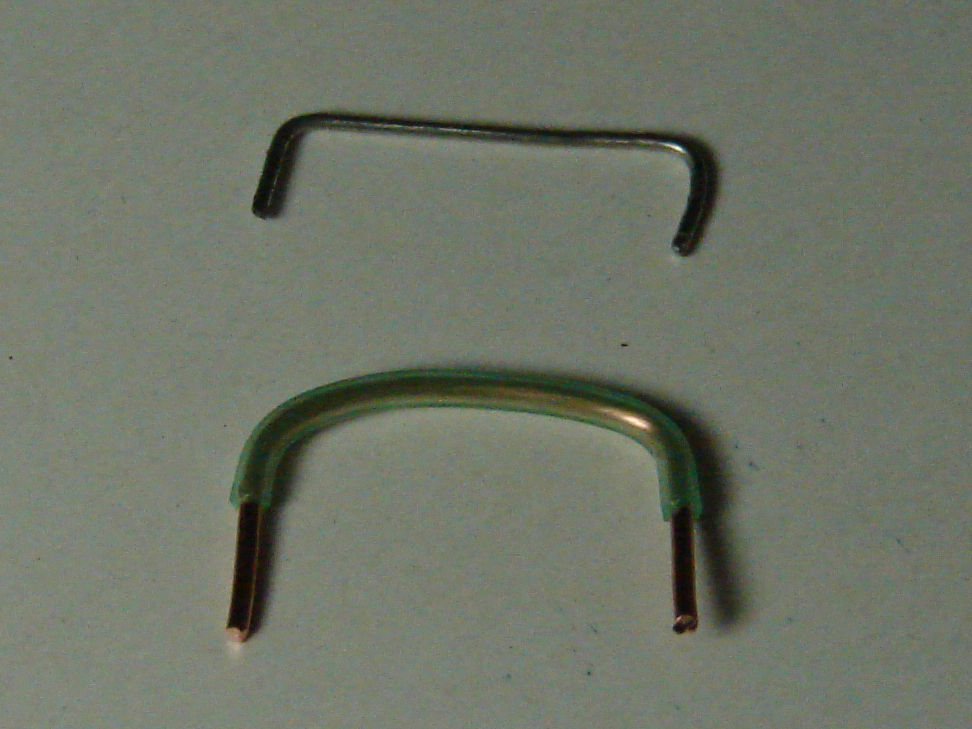
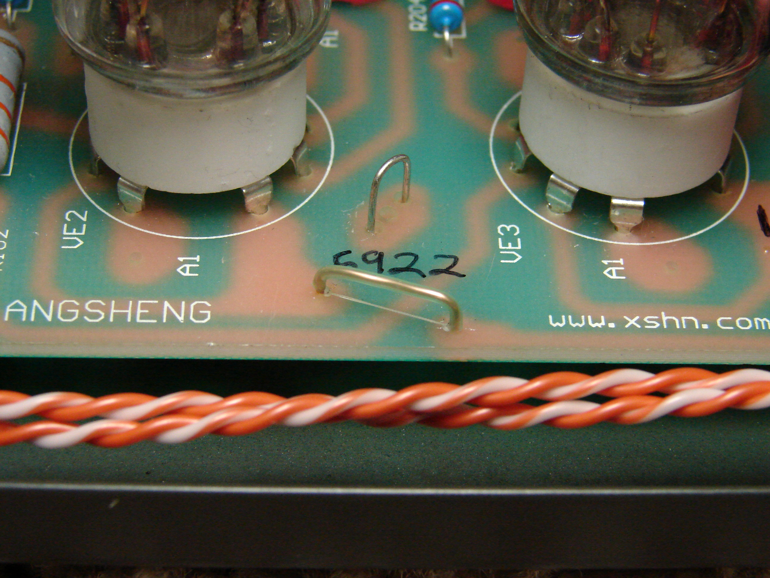
Jumper
There is also a little jumper that is in the direct signal of the right channel. I believe the stock one is made of steel so it should definitely be replaced. I used a small piece of the CAT6, but a piece of lead-wire left over from a cap or resistor would work too.

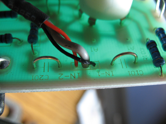
Input Caps
The input caps (C101,201) can also be replaced with jumpers if you are sure that your source puts out an acceptable amount of DC. I just used jumpers made out of CAT6 for this.

Headphone Jack
The stock headphone jack is okay, but the way it's mounted kind of sucks. I replaced mine with a SwitchCraft open-frame type designed for thick panels and I soldered the 10Ω NTE output resistors directly to it.

Intro
While the overall build quality of this amplifier isn't that bad, the quality of most of the parts is pretty low, but that's exactly why there is so much room for sonic improvement by doing modifications. One of the great things about this amp is that there is quite a bit of room inside, unlike most of the other tube amp offerings in this price range, and this makes it quite easy to add big parts such as film caps, electrolytic caps, and volume pots.
So to start off here's an inside pic of a bone stock 708B courtesy of Nugget:
Here's the schematic for the audio section courtesy of zer061zer0:
Here's the parts list:
Capacitors
C1,2 330uF 450V electrolytic - Main filter.
C6,7 150uF 200V electrolytic - Headphone output.
C8,9 33uF 450V electrolytic - Main filter bypass.
C101,201 0.1uF 50V film - Input.
C104,204 0.22uF 400V film - Interstage coupling.
C105,205 0.22uF 400V film - Preamp output.
Resistors
R101,201 1M 1/2W
R102,202 33K 2W - Anode load for 6N3.
R103,203 1K 1W - Cathode bias for 6N3.
R104,204 200R 1/2W
R105,205 220R 1W - Cathode bias for 6922.
R106,206 1M 1/2W
R107,207 1k 1w - Input.
R1 1K 2W
R2 2K 2W
R3,4 100R 1W
R7,8 100R 1W
R9,10 330K 1/4W - The value was hard to read so I'm not 100% positive on this one.
R1,2 10R 1W - Headphone output.
Misc
Vol Pot - 100K stereo audio/log taper
D1,2 1N4007 1A 1000V diodes
Screws - M3 x 0.5mm
Safety
Before I get into the main mods, I would like to touch upon a few things concerning safety while working on this amp. First and foremost is the fairly HV (~220VDC) that is present while the amp is powered up. If you are ever taking measurements in the circuit with your DMM while the power is on, it is recommended to keep one of your hands behind your back. Doing this eliminates the possibility of your body forming a path for HV to travel through, which could be fatal. It's a good habit to get into while measuring tube amps or anything electrical for that matter.
The other main thing to keep in mind is that the big 330uF filter capacitors in the power supply will remain charged for quite a while. So even if you unplug the amp there is still a considerable shock hazard with these big caps. Many amps employ bleeder resistors on the filter caps to safely drain them as soon as the power is tuned off. Unfortunately the XS 708B doesn't have these, so I'd highly recommend adding these as your first mod, especially if you plan on taking this amp apart a lot to do extensive mods. Anything from about 50KΩ to 200KΩ will be okay for this purpose. I soldered a 2W resistor to both of the caps to divide the heat to be dissipated into two resistors. If you used a 100KΩ resistor on each cap, then they will dissipate about 1/2 watt each. If you used a 150KΩ resistor on each cap, then they will dissipate about 1/3 watt each. Adding these resistors will drain the filter caps within a few minutes of the power being turned off. In the mean time you could just use something like a 25KΩ resistor with a pair of alligator clip wires to manually drain these caps.
Bleeder resistors added:
Another simple power supply mod that I recommend is replacing R1 and R2 in the power supply with higher wattage resistors. This isn't really necessary, but in my amp these two resistors were getting pretty hot. For R2 (2KΩ) I used a 3W NTE with plenty of space around it for good air circulation. R1 (1KΩ) is situated in between the two filter caps so I wanted to do something different here since the larger size of a 3W would bring it pretty close to the caps themselves, which could potentially heat them up. So for this I crafted an equivalent 1KΩ 4W resistor using four 1KΩ 1W resistors in series/parallel. This is ideal here since it gives plenty of power handling, good clearance in between the caps, and much better air circulation.
1KΩ 4W combo resistor:
Crucial Mods
The mods in this group are the ones that I feel make the biggest improvement in the sound. If you want to know what will give the biggest bang for the buck, this is where to start. This crucial group includes the volume pot, the input resistors, the interstage coupling caps, the output caps, and the output resistors.
Volume Pot
The stock volume pot is a very cheap carbon type and it suffers from pretty severe channel imbalance. This is especially a problem in the 7 to 8 o'clock range, which is right in the range where you'll be the majority of the time due to the very high gain of the 708B. I measured how much difference there was between the two channels for this pot at a few different rotations and it averaged about 2000Ω, which is why it has such horrible channel balance. I upgraded this to a 100KΩ ALPS stereo pot and I was very surprised by how much this helped with the clarity. The size of the soundstage increased a bit as well, which was especially noticeable with instruments that are panned far to one side.
There's a few notes about doing this mod. The threaded barrel of the ALPS is slightly larger than the stock pot so you will have to enlarge the mounting hole a little bit. I did this by hand so I don't know what size drill bit is required. A new hole will also have to be drilled to locate the little tab on the ALPS that keeps it from rotating and I would recommend locating this hole to orient the pot with the pins facing up since this gives good access to them for later when upgrading the signal wire. The knob that I used is from Rat-Shack and since it's made for a 1/4" shaft I had to wrap a single layer of electrical tape around the shaft of the ALPS 6mm shaft for the knob to be centered. This particular knob almost fits into the circular recess milled into the faceplate and with a little bit of sanding to the knob's outer edge it'll fit inside.
Detail of new hole for tab and tape wrap:
Input & Output Resistors
Both pairs of these resistors are directly in the audio path and since low quality film resistors have the potential to be noisy I'd definitely change these four resistors. This is a very simple mod and there is a wide choice of options for these. You could just play it safe and use some nice metal films like PRP or Vishay/Dale, you could try something different like some RIKEN carbon films, or you could get crazy and go with some Audio Note tantalum film resistors here like some of us have. The input resistors are 1KΩ 1/2W (R107,207) and the headphone output resistors are 10Ω 2W (R1,2 *note that these two resistors share the same part number as the two resistors previously mentioned in the power supply so be careful).
RIKEN input resistors:
NTE output resistors on HP jack PCB:
Interstage Coupling Caps
The stock caps here are WIMA metallized mylar so there is definitely room for improvement. Changing these caps (C104,204) has a pretty big affect on the sound, right up there with the changing the volume pot. I went with Auricaps for these, but I would recommend the Mundorf M-Cap ZN as a better choice for around the same price. Like the input/output resistors this is a very easy mod. For those who also plan on using the preamp output of the 708B I would upgrade C105,205 as well.
Headphone Output Caps
The stock ones are just some cheap 150uF electrolytic caps and needless to say these can be significantly improved upon. If you are using lower impedance cans I would increase their uF value, which lowers the frequency at which the bass rolls off. Since I use 300Ω cans I just went with 200uF here in the form of two ELNA 100uf 250V caps paralleled per channel. Whatever you end up using just make sure it's rated for at least 250V to be safe and make sure you observe polarity when installing these.
Other Signal-Path Mods
This is all the other stuff in the signal path that could be upgraded after the crucial mods above. This includes the RCA jacks, signal wire, jumper, input caps, and HP jack. Upgrading these still helps, just not nearly as much as the above group.
RCA Jacks
The RCA jacks in my amp were of very low quality and one was undersized enough to let the IC easily fall off. The solder job on these was also horrible. I replaced these with some Teflon Calrad RCA jacks. The mounting holes are 3/8" so any standard RCA jack will work.
Stock jacks:
Calrad jacks:
Signal Wire
The signal wire used in this amp is of fairly low quality as is the solder job on them. I used some Belden 7882A CAT6 Teflon wire to replace this since it's easy to work with and very affordable. Even though the stock wire is shielded I haven't had the slightest problem with hum by using this wire. Of course there are many options for wire here, but I would use something smaller than 20ga to avoid having to enlarge the holes in the PCB with a small drill bit.
Stock vs. Belden CAT6 wire:
Amp with Belden CAT6 wire throughout:
Jumper
There is also a little jumper that is in the direct signal of the right channel. I believe the stock one is made of steel so it should definitely be replaced. I used a small piece of the CAT6, but a piece of lead-wire left over from a cap or resistor would work too.
Input Caps
The input caps (C101,201) can also be replaced with jumpers if you are sure that your source puts out an acceptable amount of DC. I just used jumpers made out of CAT6 for this.
Headphone Jack
The stock headphone jack is okay, but the way it's mounted kind of sucks. I replaced mine with a SwitchCraft open-frame type designed for thick panels and I soldered the 10Ω NTE output resistors directly to it.
Last edited: