brschmid
500+ Head-Fier
- Joined
- Mar 6, 2003
- Posts
- 700
- Likes
- 10
Last Update 08-29-2004
[size=xx-small]please do not PM with specific questions, i hardly have time to browse these forums weekly, so if you PM me a question, it will most likely not be answered, just post in the thread, there are many knowledible folks here. [/size]
There are 3 guides, mini-mini, mini-RCA, RCA-RCA. The Pics are at the end, in the Reference Pics section. Also be sure to check out the comments.
The links work as of Aug. 29th, 2004; if the links don't work, (It appears that Markertek changes their links daily), just search for the part number and you will find them
Tools:
Wire stripper
Side cutters
Soldering Iron
Solder
Multimeter is very helpful
30 minutes of your time
Building materials: (they are links)
Wire; your choice what and from where, these are what I like:
Canare Star Quad or Mini Star Quad, Pacific Radio also has it; if you choose star quad use the white wire for the signalsee page 4 for explanation.
Homegrown Audio Silver Braid
CAT5E network cable works pretty nice too
there are also many other good choices for wire out there, don't limit yourself to these
Connectors; Your choice again:
right angle:
Switchcraft 35HDRANN If this link doesn't work, search for the part number at markertek and you will it
straight plug:
Switchcraft 35HDNN If this link doesn't work, search for the part number at markertek and you will it
Canare F-12 If this link doesn't work, search for the part number at markertek and you will it
RCA:
HGA Rhodium
Good selection of others from Parts Express
TechFlex and Heatshrink:
I have a another thread about this with many links, here
I use 3/8" to cover Starquad or similar size cable. it doesn't stretch to much and still looks good.
[size=small]Mini-Mini cable: [/size]
Switchcraft plugs in the pic

Step 1: Refer to Pic 0
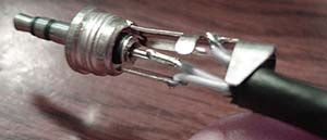
Check out your contacts on the plugs and determine what connection corresponds the each 1/3 of the plug. This will help you when you are assembling so you don't solder the same wire to 2 different points. The tip or the connector is Left, the middle is Right, and the base is ground.
Step2: Reference Pics 1 and 2
In the case of Canare Star Quad(but I am sure the other wire types are similar), strip of about 3/4" of the rubber insulation, then you will see some metal braid surrounding the inner wires, cut that off as well. You can also cut your wire to length now or before you add the other connector to the other end, it is up to you. I personally wait so i can maximize my bulk cable.
Step3: Reference Pic 3
Now you will see 4 wires. Pick 2 of them and designate them as ground and then the other 2 are left and right. Cut the insulation off the ground wires and solder them to the part of the plug that corresponds to ground, usually the part of the connector that has the most surface area and has threading on it for the cover to screw on to.
Step 4: Reference Pic 3
Pick a connection point and solder 1 wire to it, then do the same with other wire/connection point. Clamp the wire in place, then put on the plastic insulation sleeve and screw on the cover.
Step 5: Refer to Pic 5
Cut down your excess wire to length and DONT Forget to slide on the Sleeve and Cover(I have done this, Refer to Pic 4, I did this again
 ). This is a good time to add your Covering if you are going to, it is hard to do when the cable is complete.
Repeat Steps 3 and 4, just make sure to connect the same wires to the same points.
Step 6:
Test for continuity between the cables at each 1/3 of the plug with the other side. and then enjoy.
Notes:
I have only used Canare Star Quad cable, i found the Mini Star Quad too small in diameter.
The next cable i make is gonna be longer than my current one and i think i am gonna use Canare F-12 connectors becuase i don't need the right angles.
[size=small]mini-RCA:[/size]
Canare F-12 and HGA RCA's in pic

Step 1:
Start with your basic mini-mini steps, making sure to use 2 wires for ground when using the 4 conductor wire.
You could use 2 different 2-conductor wires for this, so you wouldn't have to cut the casing on the cable to split it into the 'Y' shape, but I think using a single 4 conductor cable is easiest.
Step 2:
Then, if you are using 4 conductor wire, cut off the casing and make 2 pairs out of the 4 individual wires. One pair for the left RCA and one for the right RCA.
Add your covering now if you are going to cover the wire.
Step 3:Refer to Pic 6
Put the cover for the RCA on the wire before soldering (Pic 4 again)Take the ground from the first pair of wires and solder it to the ground connection point on the RCA, then take the signal wire and solder it to the middle pin connection point. Take note of which channel it is, either left or right. Then repeat for the other RCA.
[size=small]RCA-RCA:[/size]

For this one, you will only need 2 conductor wire. Refer to Step 3 from the mini-RCA instructions.
[size=small]Reference Pics[/size]
0

1

2

3

4 you definitely don't want to be in this position, DOH!!!!

5 finished connector

6 RCA connector

7 'Y' split for mini-RCA

[size=large]An Addition by infiskik[/size]
Im not going to do the walk through like brschmid already did but i will do a pic by pic sequence, with a tiny
description of each.
1. some supplies
A. Star Quad with Techflex on it.
B. 3 extra pieces of quad cable
C. 2 extra pieces of techflex
D. SwitchCraft straight plugs, ones mentioned by brschmid (plugs, barrels, and sleves)
E. Canare plugs, ones mentioned by brschmid.
F. My Kershaw onion knief w/ half serated blade (best wire stripper ever by personal opinion )
)

2. cabl stripped bout 1/2 inch. shows the rubber outside, metal braid, thread, and wires in their natural twist.

3. Cable stripped. see picture for explanation.

4. cable stripped and conductor wires stripped and seperated. barrels and sleves PUT ON.

5. solder points unsnipped. marked 1 2 3, 3 is ground, look at brschmids post for other 2 (its 2am i forget)

6. solder points snipped. still marked 1 2 3.

7. solder points from other end of cable still 1 2 3. (i bent the prongs a tad to make it easier on myself)

8. finished 8 inch cable, with orange star quad and grey techflex, and the switch craft plugs.

Ok, thats the assembly steps, these next pictures go over some tips i figured out to make things a tad easier on
yourself, or atleast they did for me.
1. i think brschmid went over this, but be carefull on how much of the rubber you strip off, and take the time to
compare the depth of the plug and its conenctors. on the first 12 inch cable i made with the grey star quad i
stripped a little too much rubber off and the crappy radioshack plug was not that deep. well as you can see the the
plug isnt deep enough for the amount of rubber i stripped, so i have this horrid gap. i plan to fix it with heat shrink later.

2. when putting the the techflex on i suggest leaving a tad off since its not expanded you can slip the barrel and
sleve on the cable and flex much easier. youll figure it out pretty quick since the ends of techflex tend to frey
quite bad when trying to slide it on the cable. Also its not the easiest thing to pull on the cable to being with,
but it works like a chinese finger trap, so push it together and then slide it on. And if you look in the assembly
pictures i have the edge of the stripped area taped with blue painters tape (doesnt leave sticky residue) to hold
the techfex tight so it doesnt frey while working on the inner wires.

3. The hardest thing i had to figure out was how to tell which wires were which on the other end. I didnt want to
spend 80 bucks or so on a multimeter, since i didnt have one already. so i did a little improvising. I used a
LED(2)and 4 tiny button cell batteries(1). I stripped all 4 of the inner wires on one side of cable, and only 2 on
the other. i hooked the batteries to the end with the 2 exposed wires(3), then tested each wire on the other side
systematically with the LED. ghetto but it worked.
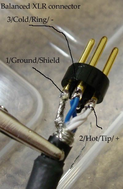
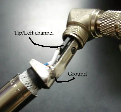
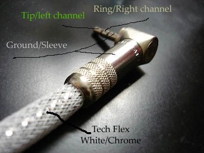
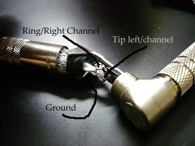
Other reference pics courtesy of RnB180
XLR Connector
RA switchcraft connector
Switchcraft connector
[size=xx-small]please do not PM with specific questions, i hardly have time to browse these forums weekly, so if you PM me a question, it will most likely not be answered, just post in the thread, there are many knowledible folks here. [/size]
There are 3 guides, mini-mini, mini-RCA, RCA-RCA. The Pics are at the end, in the Reference Pics section. Also be sure to check out the comments.
The links work as of Aug. 29th, 2004; if the links don't work, (It appears that Markertek changes their links daily), just search for the part number and you will find them
Tools:
Wire stripper
Side cutters
Soldering Iron
Solder
Multimeter is very helpful
30 minutes of your time
Building materials: (they are links)
Wire; your choice what and from where, these are what I like:
Canare Star Quad or Mini Star Quad, Pacific Radio also has it; if you choose star quad use the white wire for the signalsee page 4 for explanation.
Homegrown Audio Silver Braid
CAT5E network cable works pretty nice too
there are also many other good choices for wire out there, don't limit yourself to these
Connectors; Your choice again:
right angle:
Switchcraft 35HDRANN If this link doesn't work, search for the part number at markertek and you will it
straight plug:
Switchcraft 35HDNN If this link doesn't work, search for the part number at markertek and you will it
Canare F-12 If this link doesn't work, search for the part number at markertek and you will it
RCA:
HGA Rhodium
Good selection of others from Parts Express
TechFlex and Heatshrink:
I have a another thread about this with many links, here
I use 3/8" to cover Starquad or similar size cable. it doesn't stretch to much and still looks good.
[size=small]Mini-Mini cable: [/size]
Switchcraft plugs in the pic
Step 1: Refer to Pic 0
Check out your contacts on the plugs and determine what connection corresponds the each 1/3 of the plug. This will help you when you are assembling so you don't solder the same wire to 2 different points. The tip or the connector is Left, the middle is Right, and the base is ground.
Step2: Reference Pics 1 and 2
In the case of Canare Star Quad(but I am sure the other wire types are similar), strip of about 3/4" of the rubber insulation, then you will see some metal braid surrounding the inner wires, cut that off as well. You can also cut your wire to length now or before you add the other connector to the other end, it is up to you. I personally wait so i can maximize my bulk cable.
Step3: Reference Pic 3
Now you will see 4 wires. Pick 2 of them and designate them as ground and then the other 2 are left and right. Cut the insulation off the ground wires and solder them to the part of the plug that corresponds to ground, usually the part of the connector that has the most surface area and has threading on it for the cover to screw on to.
Step 4: Reference Pic 3
Pick a connection point and solder 1 wire to it, then do the same with other wire/connection point. Clamp the wire in place, then put on the plastic insulation sleeve and screw on the cover.
Step 5: Refer to Pic 5
Cut down your excess wire to length and DONT Forget to slide on the Sleeve and Cover(I have done this, Refer to Pic 4, I did this again
Repeat Steps 3 and 4, just make sure to connect the same wires to the same points.
Step 6:
Test for continuity between the cables at each 1/3 of the plug with the other side. and then enjoy.
Notes:
I have only used Canare Star Quad cable, i found the Mini Star Quad too small in diameter.
The next cable i make is gonna be longer than my current one and i think i am gonna use Canare F-12 connectors becuase i don't need the right angles.
[size=small]mini-RCA:[/size]
Canare F-12 and HGA RCA's in pic
Step 1:
Start with your basic mini-mini steps, making sure to use 2 wires for ground when using the 4 conductor wire.
You could use 2 different 2-conductor wires for this, so you wouldn't have to cut the casing on the cable to split it into the 'Y' shape, but I think using a single 4 conductor cable is easiest.
Step 2:
Then, if you are using 4 conductor wire, cut off the casing and make 2 pairs out of the 4 individual wires. One pair for the left RCA and one for the right RCA.
Add your covering now if you are going to cover the wire.
Step 3:Refer to Pic 6
Put the cover for the RCA on the wire before soldering (Pic 4 again)Take the ground from the first pair of wires and solder it to the ground connection point on the RCA, then take the signal wire and solder it to the middle pin connection point. Take note of which channel it is, either left or right. Then repeat for the other RCA.
[size=small]RCA-RCA:[/size]
For this one, you will only need 2 conductor wire. Refer to Step 3 from the mini-RCA instructions.
[size=small]Reference Pics[/size]
0
1
2
3
4 you definitely don't want to be in this position, DOH!!!!
5 finished connector
6 RCA connector
7 'Y' split for mini-RCA
[size=large]An Addition by infiskik[/size]
Im not going to do the walk through like brschmid already did but i will do a pic by pic sequence, with a tiny
description of each.
1. some supplies
A. Star Quad with Techflex on it.
B. 3 extra pieces of quad cable
C. 2 extra pieces of techflex
D. SwitchCraft straight plugs, ones mentioned by brschmid (plugs, barrels, and sleves)
E. Canare plugs, ones mentioned by brschmid.
F. My Kershaw onion knief w/ half serated blade (best wire stripper ever by personal opinion
)
2. cabl stripped bout 1/2 inch. shows the rubber outside, metal braid, thread, and wires in their natural twist.
3. Cable stripped. see picture for explanation.
4. cable stripped and conductor wires stripped and seperated. barrels and sleves PUT ON.
5. solder points unsnipped. marked 1 2 3, 3 is ground, look at brschmids post for other 2 (its 2am i forget)
6. solder points snipped. still marked 1 2 3.
7. solder points from other end of cable still 1 2 3. (i bent the prongs a tad to make it easier on myself)
8. finished 8 inch cable, with orange star quad and grey techflex, and the switch craft plugs.
Ok, thats the assembly steps, these next pictures go over some tips i figured out to make things a tad easier on
yourself, or atleast they did for me.
1. i think brschmid went over this, but be carefull on how much of the rubber you strip off, and take the time to
compare the depth of the plug and its conenctors. on the first 12 inch cable i made with the grey star quad i
stripped a little too much rubber off and the crappy radioshack plug was not that deep. well as you can see the the
plug isnt deep enough for the amount of rubber i stripped, so i have this horrid gap. i plan to fix it with heat shrink later.
2. when putting the the techflex on i suggest leaving a tad off since its not expanded you can slip the barrel and
sleve on the cable and flex much easier. youll figure it out pretty quick since the ends of techflex tend to frey
quite bad when trying to slide it on the cable. Also its not the easiest thing to pull on the cable to being with,
but it works like a chinese finger trap, so push it together and then slide it on. And if you look in the assembly
pictures i have the edge of the stripped area taped with blue painters tape (doesnt leave sticky residue) to hold
the techfex tight so it doesnt frey while working on the inner wires.
3. The hardest thing i had to figure out was how to tell which wires were which on the other end. I didnt want to
spend 80 bucks or so on a multimeter, since i didnt have one already. so i did a little improvising. I used a
LED(2)and 4 tiny button cell batteries(1). I stripped all 4 of the inner wires on one side of cable, and only 2 on
the other. i hooked the batteries to the end with the 2 exposed wires(3), then tested each wire on the other side
systematically with the LED. ghetto but it worked.
Other reference pics courtesy of RnB180
XLR Connector
RA switchcraft connector
Switchcraft connector


