Quote:
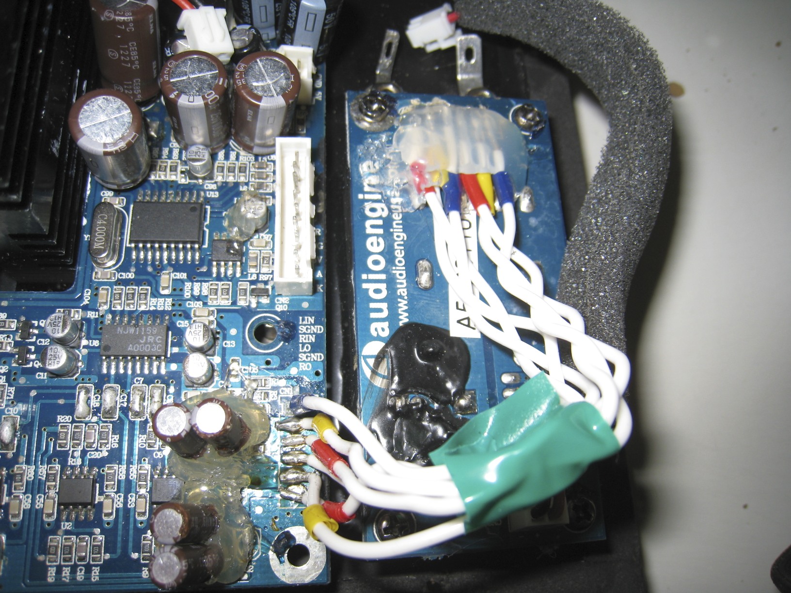
The volume/LED cable is intact and I put some hot glue on there.
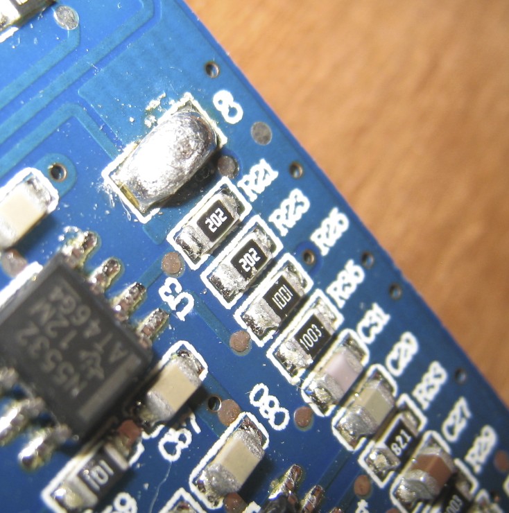
I cleaned up the resistor area with some isopropal and it's now nice and clean. Well, not nice but very clean. It does look a whole lot better than it did in the photo I posted. Should be workable.
Thank you for checking that resistor. It's a pain to take out your amp board, certainly, so there is no big hurry. I'll have to buy one of your cables to repay you!! I dig your website. Is the business up and running?? I'm serious about checking out your cables.
OK, one quick question... in one of photos of your right crossover, what's the purpose of the wires you soldered on the bottom of the board?? See red lines in the photo below.
Haha, good job gluing the volume knob wires down!
Hope that wasn't too hard for ya.
Nice and clean will surely make the job more workable.
I'll have the resistance value for you by today along with a link to purchase it online.
Shouldn't be over $2 for 100 pieces.
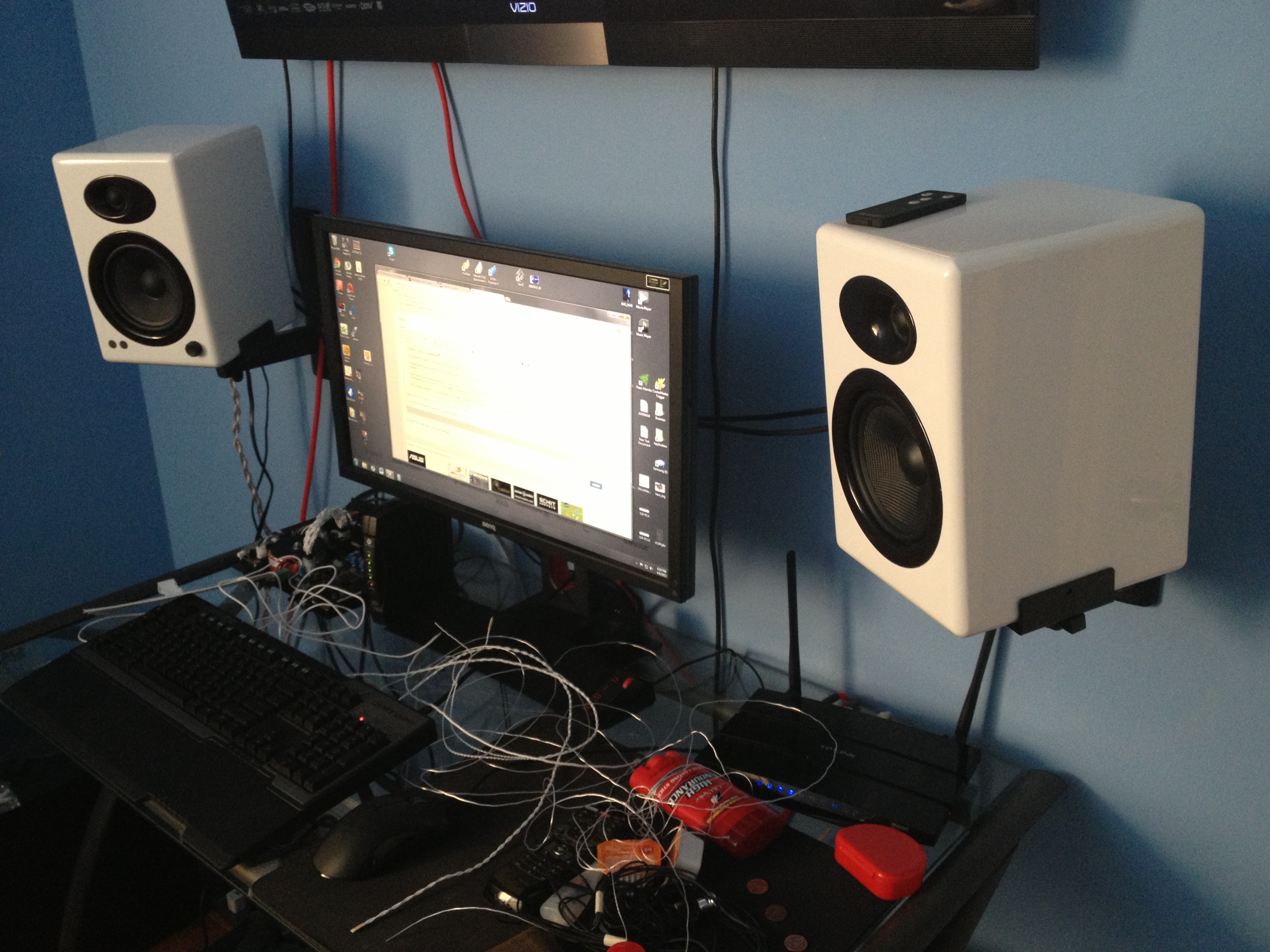
I have my speakers mounted to the wall, so i'll have to take down the left one and open the back, shouldn't be a problem.
You might want to get one of these Pinpoint AM-40 wall mounts.
Having it angled and pointed at your ears improve you so much as an audience.
It's way better than just having it sitting on a desk and "blowing" music by you, right past the torso.

Business is ok, all HTML coding (for the website) was left on a hard drive that then.. err.. kind of died.. so i now have to start from scratch.
If you're ever need a cable (any kind), do let me know.
To address your question.
I'm a cable guy, I believe a lot about conductance and impurities (from metals that don't conduct so well).
The left side speaker crossover is connected by wires, being wires, you can choose the quality.
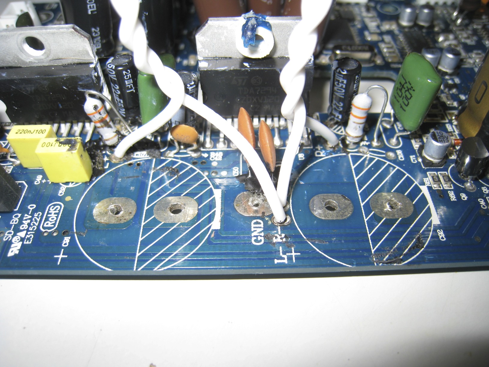
It isn't the same for the right as it's connected to the tin plating, that's why i kind of ditched that and went with a straight wire.
The higher conductance of that wire, should make that pathway more accessible (for signal) than the tin plate with the mounting screw.
I simply soldered a silver plated copper wire to that copper ring, then soldered it onto the brass outpost.
You might not want to try it, since the solder won't stick to the brass, unless you use like insanely high temperatures.
It ended up melting the plastic that held it a bit, but didn't really bother me.
As long as the wire touches or wraps around outpost, then you should be good.
I say just solder the wire to the copper rings, (but leave a good length) then wrap it around each post (on appropriate size).
I noticed you copied my idea to dampen the crossover pcb, how cute haha.
Did you source your parts from Parts Connexion? I see the M-Resist.
When i tried to buy it there, they only had one in stock, so i had to go to Madisound for mine.
Tim