


ramachandra
100+ Head-Fier
- Joined
- Jan 5, 2012
- Posts
- 181
- Likes
- 30
Almi's X-Fi Mod
I have got big inspiration a while ago from Layman's Guide to modify my good old X-Fi. Since I have learnt few things and tricks to improve the X-Fi further more. What I would like to share here is nothing special, most of them well known, but You can save time to read them in one place.
Since X-Fi XtremeMusic, few other soundcards appeared on the market, usually with more extras and better quality. Some can say that: what is the point to upgrade this old outdated modell, it will be never-ever as good as my new shiny 200$ card. If we are loking the technical data they are correct. In reality, this mod can outperform a basic Auzentech X-Fi Forte or Titanium HD card in many ways (I have them both). Even some external DACs as well. It is amazing how much hidden potency remains in this card after many years.
This modification is working on the same way on XtremeMusic and Xtreme Gamer Fatality Pro.
What you need for this upgrade:
Opamps:
4pcs OPA1602AID (for all chanels, no adapters required)
Soldering:
soldering paste (basic is perfect)
soldering iron (narrow head important)
solder (cheap=trouble)
solder sucker
wire cutter
twezers
Clock:
ultra precision 1ppm TCXO 24.576MHz
Capacitors:
16pcs Elna Silmic II 22uf 16V
1pcs Elna Silmic I, II 1500uf 16V or 1000uF 16V
1pcs Elna Silmic I, II, or Cerafine 47uf 16V
3pcs Elna Silmic I, II or Cerafine 10uf 50V
2pcs Elna Silmic I, II, or Cerafine 22uf 16V
1pcs Elna Tonerex 100uf 50V or Silmic II 100uF 25V
6pcs 0.1uf 63V Wima MKS or other brand MKT capacitors
About components:
Opamps:
LM4562: Few years passed, they are better then stock OpAmps but outdated. Very sensitive to noises, what is abundant inside your pc. I have found many of them faulty.
Opa228P: One of the best opamp highly performing in the lower range (bass and drums ect.)
(Thank you Majkel!) The 228p is the mono, 2228p is the stereo version. There are arguments about which one is the better, I personally prefer monos because the less chance for crosstalks. In most cases mono OpAmps are better. The PA series sound brighter than P, and are also good choice.
Opa627AU: have better high but less depth. Very similar to 49710NA (Titanium HD), but Opa627AU is a bit more alive.
Opa637SM: like Opa627AU just in a metal can. One of the best in clarity, instruments really alive, offer less details compared to OPA1602AID.
Opa128SM: Maybe a bit better than Opa638AU
Bursons OpAmp: Some says they are the best, but others have their doubts. (I don't have it yet for testing.)
OPA1602AID: One of the latest OpAmp from the great TI Sound Plus family. Usually OpAmps have a common weakness. Good performance in one or two ranges, and poor or limited in the other(s). This one is without such of weakness. High-End no doubt. (A noticeable thing is a tiny harshness in the midrange. Ears can quickly adapt, not enough to be disappointed) Can be solder directly to the card, no need for adapters.
OPA1612AID: A bit older close enough alternative. Better only on paper than OPA1602AID, sound more neutral in comparison.
Others: There is an ocean of them. Many of them was a great choice for upgrade around 2007 but time is time...
Great threads about OpAmps:
http://www.head-fi.org/t/397691/audio-gd-discrete-op-amps-reviewed-opa-earth-opa-moon-opa-sun-v-2
http://www.diyaudio.com/forums/chip-amps/154106-best-sounding-audio-integrated-opamps.html
Capacitors:
Elnas are one of the best electrolytic capacitors in the audio industry. In this mod they are making the sound clear and warm, easy on the ears, and more realistic 3D! Elnas naturally increase bass, Nichicons are better in the midrange and this is not coming always handy. Other than that, they are great capacitors in the right place and equipment. The difference between the audio grade capacitors and standard is the used materials and technology. Static measurements almost not shows difference in numbers, still the influence undeniably present in the sound. I recommend the following capacitors to use for the modifications:
Elna Silmic II: Most people consider them as the best for audio, warm clean analog sound impressive soundstages and details. A perfect choice for decoupling purpouse.
Elna Silmic: The sound have better body, but less resolution compared to Silmic II. I prefer them over Silmic II if the task is not decoupling.
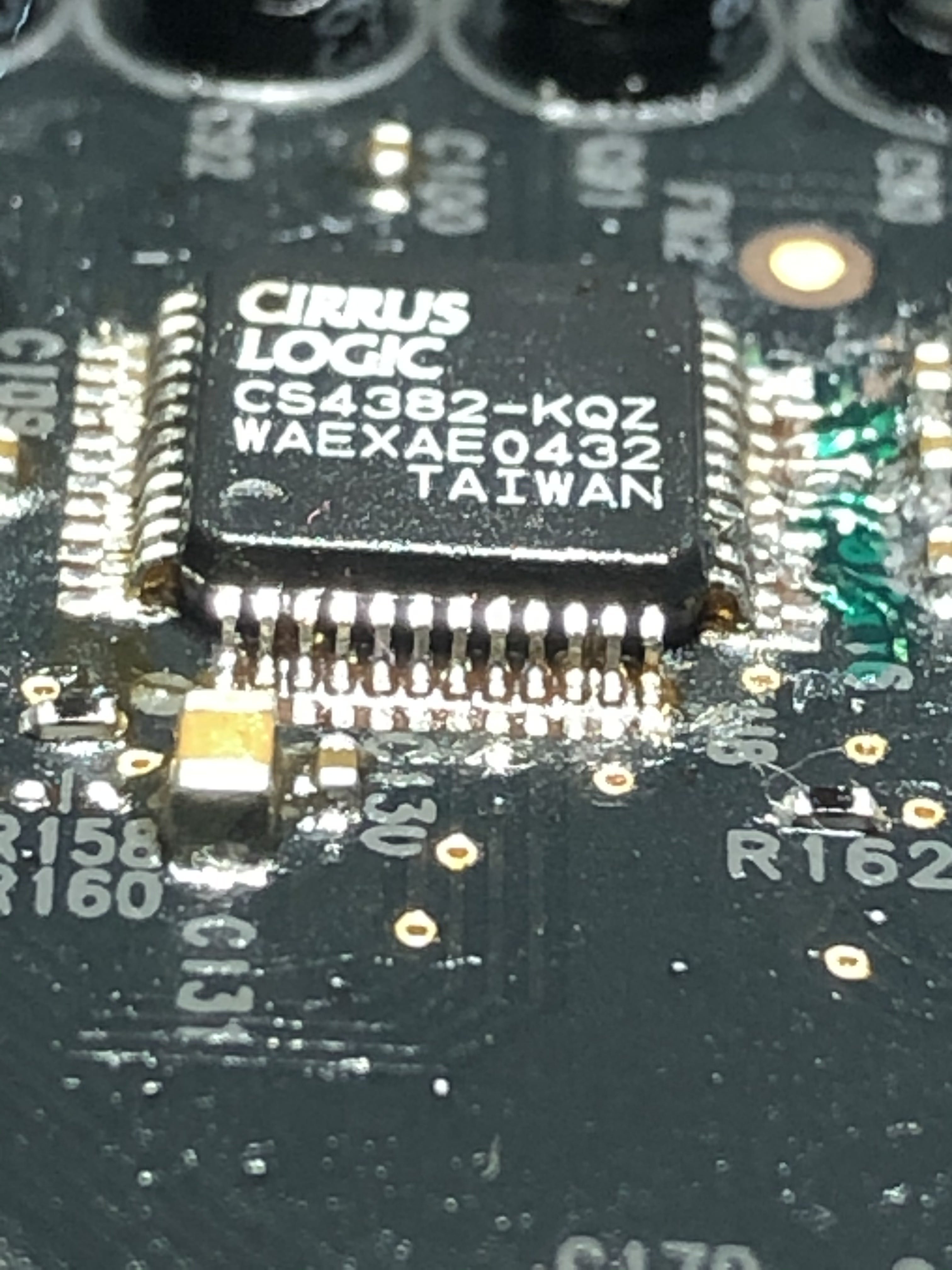
Elna Cerafine: The closest you can get to the beloved and sometimes overhyped Black gates. Neutral, precise, accurate sound, and not the best choice for decoupling. I love to use them around the DAC chip.
Nichicon KZ: Brilliant midrange and great capacitors for decoupling, but i carefully use them for other purposes because tend to sound flat to my hears. Maybe the size more than problematic.
If no better around still recommended:
Elna Tonerex: Tend to fit to places where the better Elnas do not, cheaper and sound more neutral.
Nichicon FG: Nice rounded sound good midrange and soundstages, lack of bass, smaller size and less clarity than KZ.
Nichicon ES: Excellent choice for decoupling if you love string instruments.
Of course the list can go further but i suggest to not bother with the entry level or what is hard to attain. This links are provide more detailed info about audiograde capacitors:
http://www.head-fi.org/t/528380/electrolytic-capacitors-used-in-audio-dc-blocking-comparison-tread
http://tech.juaneda.com/en/articles/electrolyticcapacitors.html
Ultra precision clock generator (TCXO):
I strongly advice to have on any soundcard. Does not matter how good soundcard you have if a cheap, lazy clock turnig the music to a foggy mess! After the change of crystal the sound becoming crystall clear, all the instruments in place, well separated. It makes the bass tighter. The 0.3ppm oscillators are better than 1ppm for a bit more money.
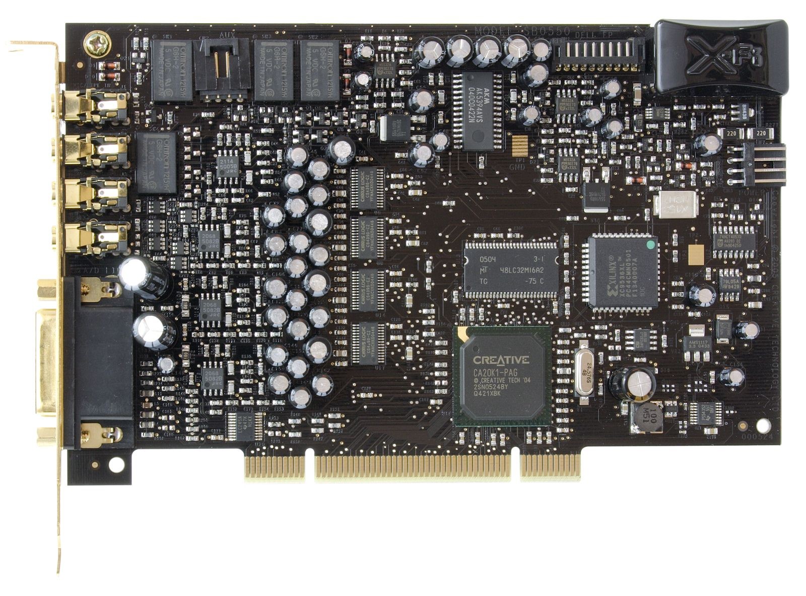
The mod
(The folloving image is not updated)

Change of capacitors
For soldering caps 60/40 Tin/Lead solder is perfect. The easy way to temove caps is to put some paste & solder to the legs first. Heat up one leg then push the capacitor to one side, then heat the other leg and push to the opposite side, then just repeat. It can ruin the cap, but who cares? To remove old solder from holes is easy if you use the solder sucker on one side, the soldering iron on the other side of the PCB. Some times solder can be really tough to remove from holes, in that case just solder the caps to the surface of the hole. Better option than keep trying and owerheat the SMDs on the card. A wet cloth or tissue can keep the critical areas cold enough from overheating.
A drill could be another option too. But remember to be very careful to select the proper head and not damage the wall of the hole. Even broken legs of the capacitors can be drilled out if necessary.
The negative polarity of electrolyte capacitors are marked on the capacitors and PCB. Using them the opposite way results problems. Film capacitors have no polarity.

Decoupling capacitors: I strongly suggest Silmic II because quality really matters. The 4 capacitors on top belong to the front speaker, the other 12 to the surround speakers. There is one rule for both group: change them all or leave them all!
Caps arround dac: This is a good place for experiments. You can not go wrong with Elna Silmic II alone here, but the same type caps can make the sound signature too strong.
Capacitor for opamps: Elna Tonerex is good for opamps. 50v capacitor is not necessary but higher voltage caps have lover ESR and longer lifetime.
Main capacitor near X-Fi chip: 1000-1500uf is enough, because Elna capacitors are naturally increase bass, and 2200uf way too much after this complete mod.
Extra capacitors: I have taken the idea from a DIY DAC. It gives extra dynamic for the sound, can reveal some hidden details.
The newly installed caps are require minimum 5 days of running to burn in. Before that, expect no miracle.
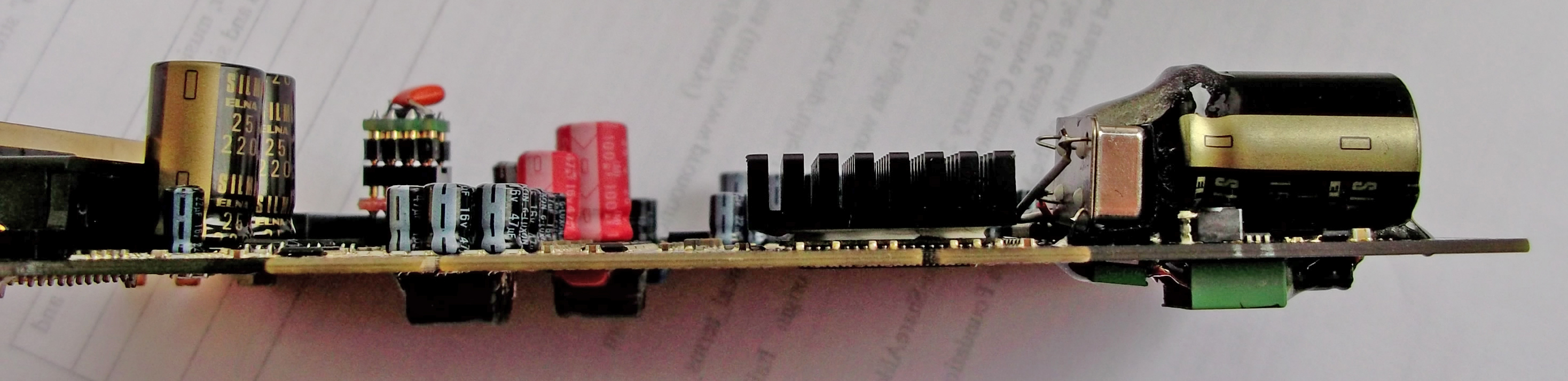
Installing the clock
To remove the chrystal can look difficult at first. Thanks to the straight legs, the trick is to push out with the head of the soldering iron, then put a screwdriver under and lift carefully.
The card has a crystal what we want to change to an oscillator. The output need to be connected to the left hole on the PCB. And we need energy for the oscillator from an 4 pin extra power connector on the the top right corner. Pin1 +5v, Pin2-3 GND (see little triangle which marks the pin1.) Then connect the floppy power cable to the card for extra juice.
If for some reason the clock doesent work, the windows7 will just be hanging on the loading screen. If it plays the sound too fast or slow, the frequency of the clock is the problem.
Update:
Linux and PCI cards: With the TCXO the there is a good chance Linux operating systems will stuck on boot screen by unknown reason. Better to leave this part of the mod unless you know how to make it work. Use 1000uF capacitor for the main chip instead of 1500-2200F for the full mod, to avoid booming sound.

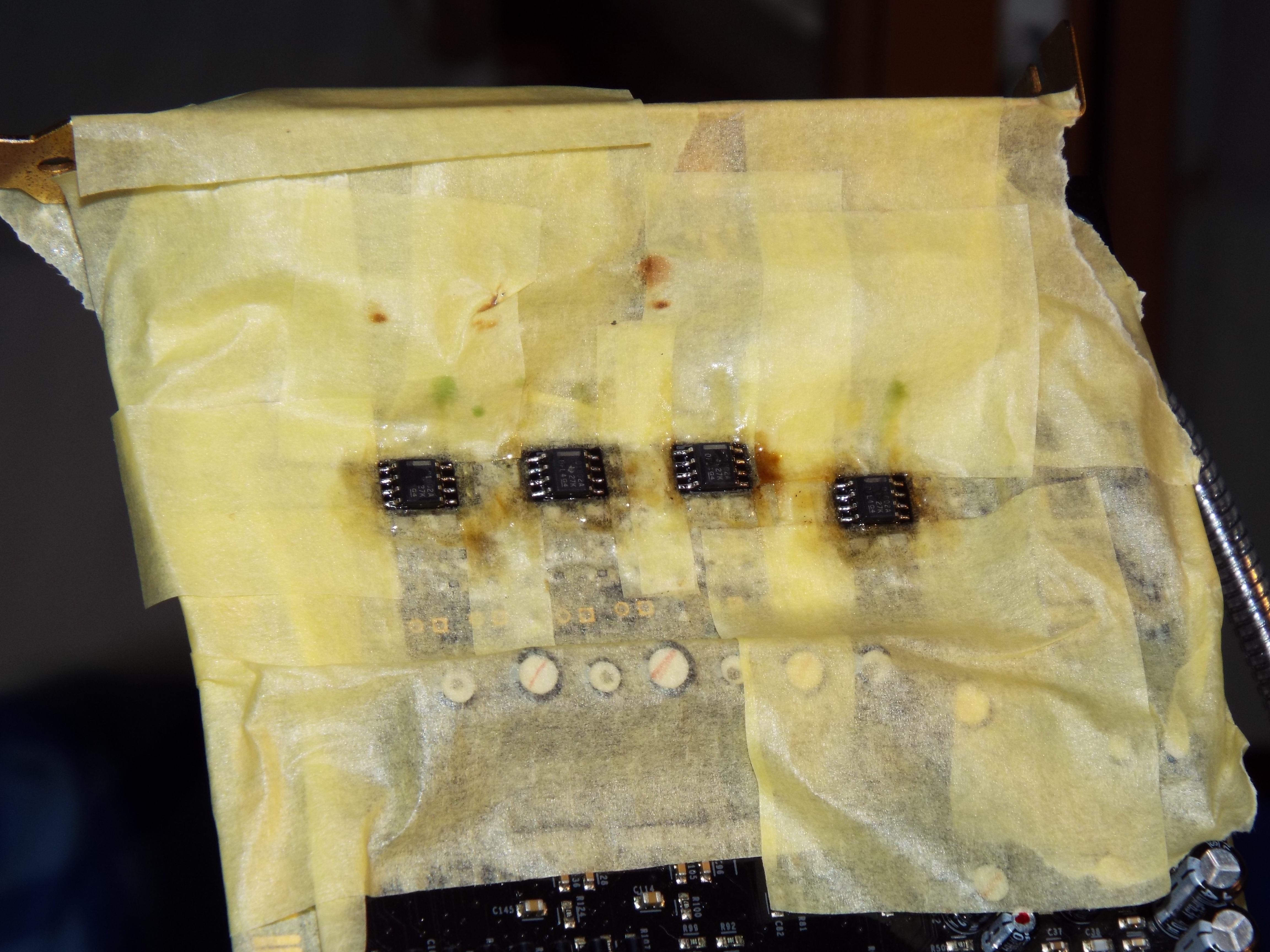
How to Remove and install OpAmps
Better to do this after the removal of the caps around the OpAmps because there is only small space for work, and this is already the most challenging part of the mod for many who try. Fine low melting point solder wire is great, the cheap low quality can be a headache, or even impossible to solder tiny things with. The first step is to remove the stock OpAmps from the board by cutting of the pins (only one in the time!) and clean the rest. Or add soldering paste, solder the pins together than heat and lift the sides. After finish use alcohol or stain remover + cotton buds to clean off the surface. Throw the old stock OpAmps to the bottom of the bin just to be sure they will be not climbing out") !
!
Soldering paste is a great help to make the solder flow so use plenty on the PCB before soldering the new chips. Start with one pin in the corner than recheck the alignment.
There is one rule about the surround OpAmps: change them all or leave them all. On the front, only one OpAmp is responsible for the left and right channel, on the surround the channels are mixed. I just mention here the sound might be heard quietly if the OpAmp(s) don`t work for some reason. If you are fortunate that is a simple soldering problem (the opposite is shortened, burnt component, damaged PCB, ect..).
Adapters
The advantage of using them is obvious if somebody like to have more experience, or simply looking for fun with the sound. The soldered connections is better than plain contacts for audio, so it make sense to stay away from them in the long term. To avoid confusion here is a picture about adapters, and a short descriptions to give an idea what they are. Basically stereo OpAmps can be used on this soundcard, or two mono with adapter(s). By the right adapter different size & package OpAmps working safely. Using a stereo OpAmp in a mono socket or any OpAmp in wrong alignment, is a predictable quick death for the component, so no shame to check the datasheet to be sure and take a second look before the power on. Since they are available on eBay for low cost i do not recommend to spend time on the homemade version.
http://www.ebay.ie/itm/1x-DIP8-SOP8-SOIC8-PCB-adapter-DIP8-SMD-Converter-DIY-/110849802208?pt=LH_DefaultDomain_0&hash=item19cf29bfe0

Making adapters
You need solid core wires, for example Sata cable and 1pcs DIP8 socket for the front and 3 more for surround (gold plated is preferable) First, remove the wires from the Sata cable, and solder 1cm L shape wires to the PCB. Start with the 2. and 4. OpAmp and make the wires short as possible then solder the DIP8 sockets to the wires. After that, use longer wires for the 1. and the 3. If they are at the same level, maybe looking better, but no space for work. The dual to mono adapter is require more space for the front channels, so better if they sitting a bit higher. Extremely important to check all the connections after soldering, because later on it will be very difficult to make corrections, and also there is a high possibility for damage during installation of OpAmps. Epoxy can be used to stabilize the wires if you are 101% sure it is working as expected.
The following picture can be used for troubleshooting. (Sorry, i do not have a proper jack to test side channels).

The alignment of the new opamps is the same as the text on the old ones. Check the marking(s) on the PCB before installation of new socket(s).

Maybe help


Not directly related to the thread, just one of my favorite video how the experts are doing things.
http://www.youtube.com/watch?v=3NN7UGWYmBY
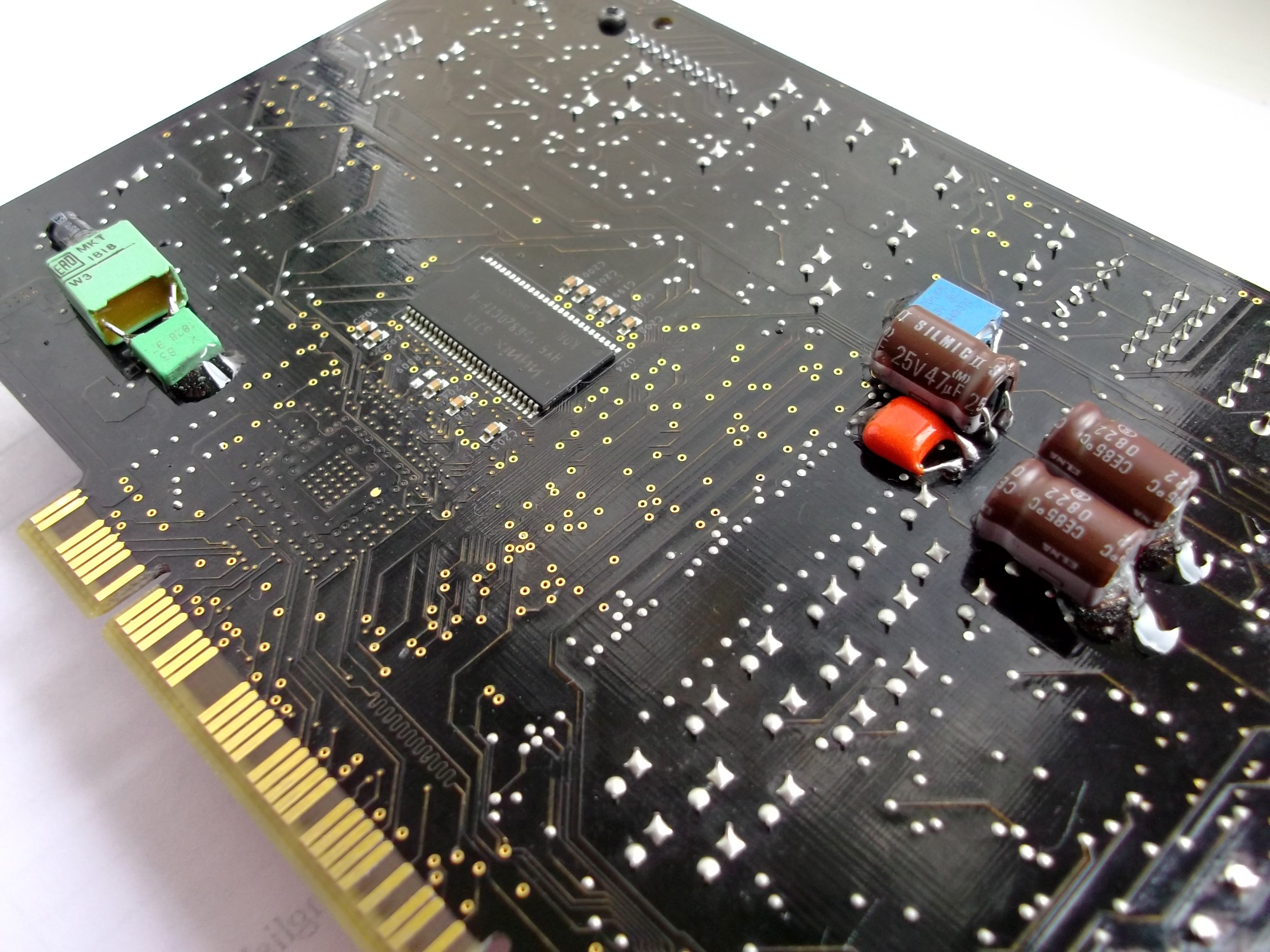
Extra Capacitors
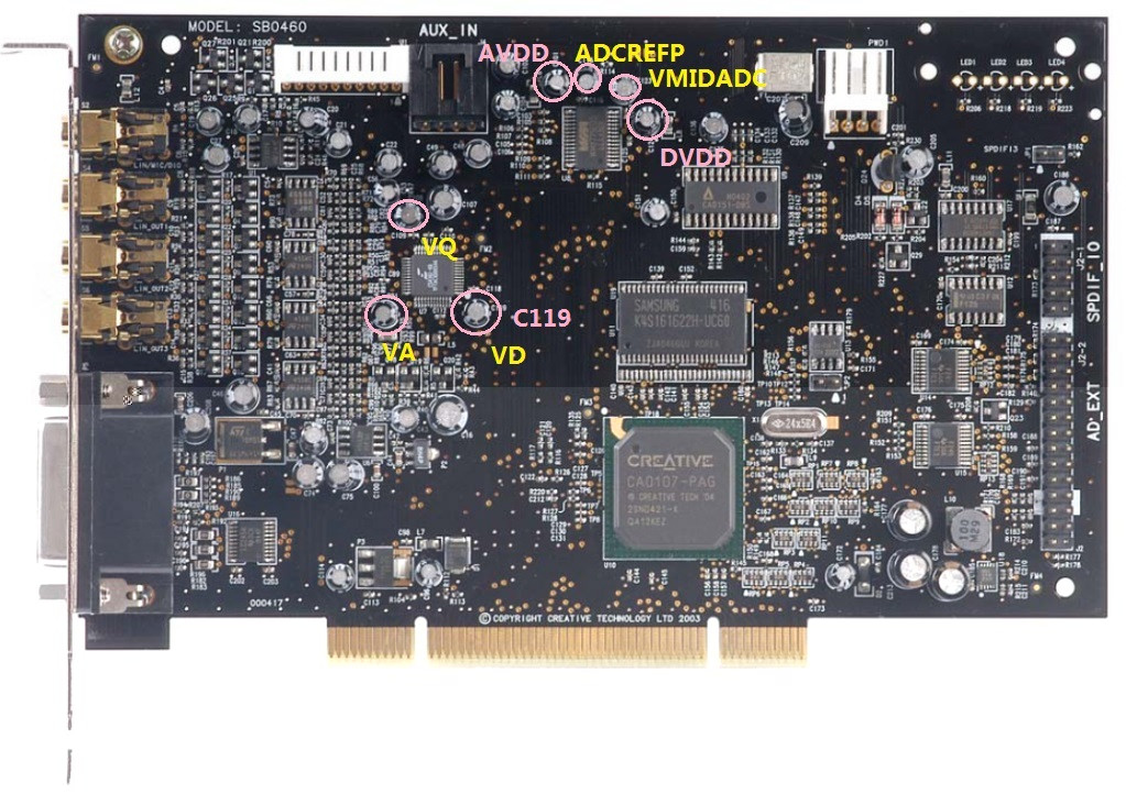
This is at least easy and working pretty good with any 0.1uf film capacitors. Simply solder them to the legs of the capacitors on the back of the card. One goes to the main cap C177 and the other 5 around the DAC chip C91,C119,C108,C56,C107. Ceramic or Tantalum is not great for audio. (I have used Soviet military K73-16 capacitor on the early versions, free from audible external noises. Technical they are superior, unfortunately in size the opposite true.)
Full bypass of muting circuits
What extra you need for this mod:
small size players
magnifying glass (min 40x)
This is a mod what you may or may not like. The removal and the bypass of the muting circuit result more clarity. The advantage brings some disadvantages as well, like hearing the not great quality in music, or the sound is more free flow, but bass is less “kicking” (a bigger cap instead of 1500uf more-less can bring back the balance).
The easy way to get rid of the components on the panel is to twist them left and right with the players. Sometimes they break into pieces, after then just clean the rest with the soldering iron.
35ohm resistors: The bypass will give a tiny improvement for the sound. Maybe some of the connected sound equipment can benefit from that if they are remaining untouched.
Front speakers: The safe way to make the connection is using a bridge-shaped wire.
Surround: Even more simple, you solder the 3 dots together (on the top side of the 6 pin transistors), and remove 46k ohm resistors.

Other tricks
- Removing all of the surround OpAmps can make an improvement if only the two front speakers required. This way the main OpAmp have a better supply of energy, and make an audible difference.
- I suggest to do the change of the caps around the DAC, and install the oscillator in the same time. Because the ultra precision clock will decrease the energy of "vibrant" sounds, the new caps around DAC will increase. They nicely compensate each other.
- Soldering chips to the PCB is risky without a temperature controlled and ESD safe soldering iron. (But not impossible)
- Shortening the decoupling capacitors not really an upgrade for the front speakers. Great for the high range & clarity but significant lose for the low range. After my disappointment on the front speakers i gave a chance for the surround, with good results. I have not experienced any negative side effects like on the front. I suggest to try it out without removing the decoupling caps. Just solder the legs together and listen...
- Soldering together the 1-7-8 pins of the OPA228p making the sound softer.
Drivers
Basically the Creative drivers are stable and reliable, still bugs are exist. The Unofficial Pax drivers are offer a solution, and much more, the installation is simple just like the original. Worth to mention the Pax sound more focused on the midrange and low is set back. If you prefer heavy bass this is not a driver for you no matter analog or digital connection you are using. You can find more details and the drivers here:
http://www.hardwareheaven.com/pax-drivers/
Fix for damaged PCB
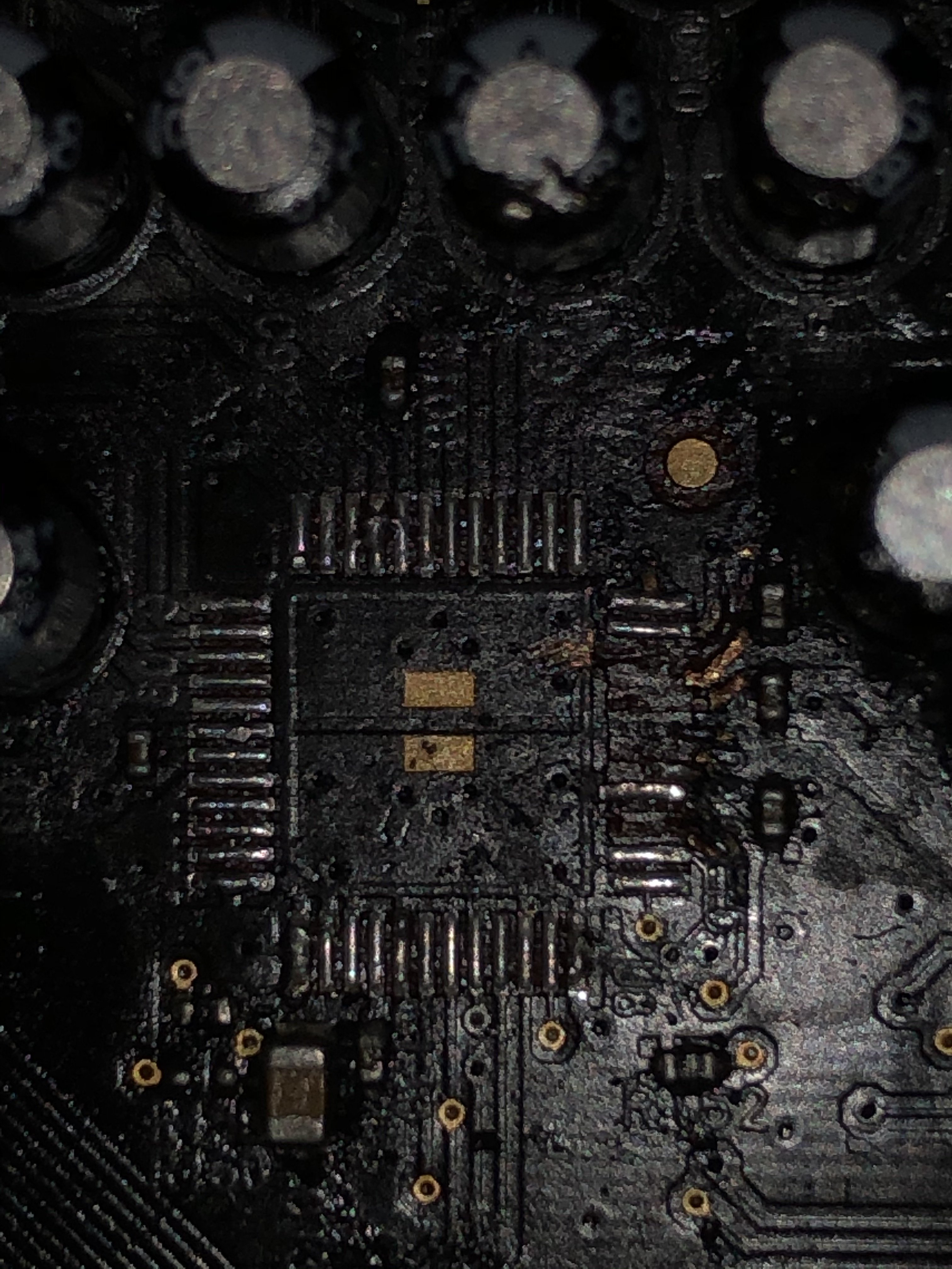
Sometimes removing the components are not going well even for experienced modders so good to know what options we have when the damage is done. The surface of the card is covered by a thin layer of paint, what is coming off relatively easy by scratching the surface with a sharp blade or other tool, revealing the real size and way the copper on the surface. It will give the opportunity to have wider surface for soldering or bridge the missing pads. Against oxidation the surface can be covered again with nail-polish if necessary. On the following picture the connections around the OpAmp can be seen.

If the hole of the capacitor damaged a very thin wire can help. Solder one side to the remaining copper and lead to the other side of the hole then install the cap, then ready for soldering as normal. Or use the other side of the PCB and the leg of the component to bridge the missing bit. Maybe not fancy, but electrons don’t care, and easier as well.
Just a bad move and SMD componets have a tendency to breaking off from the panel and not always in one piece. If the necessary value are not available try the closest you can get, or use ordinary (much bigger) 1/4Watt metal film resistors and ceramic capacitors with short legs as possible.

Source of components
What is necessary for this mod can be found on eBay, Mouser, Farnell and approximately costs 40-50€.
I'm only an enthusiastic amateur in electronic, so sorry if i can not provide more scientific approach for this mod.
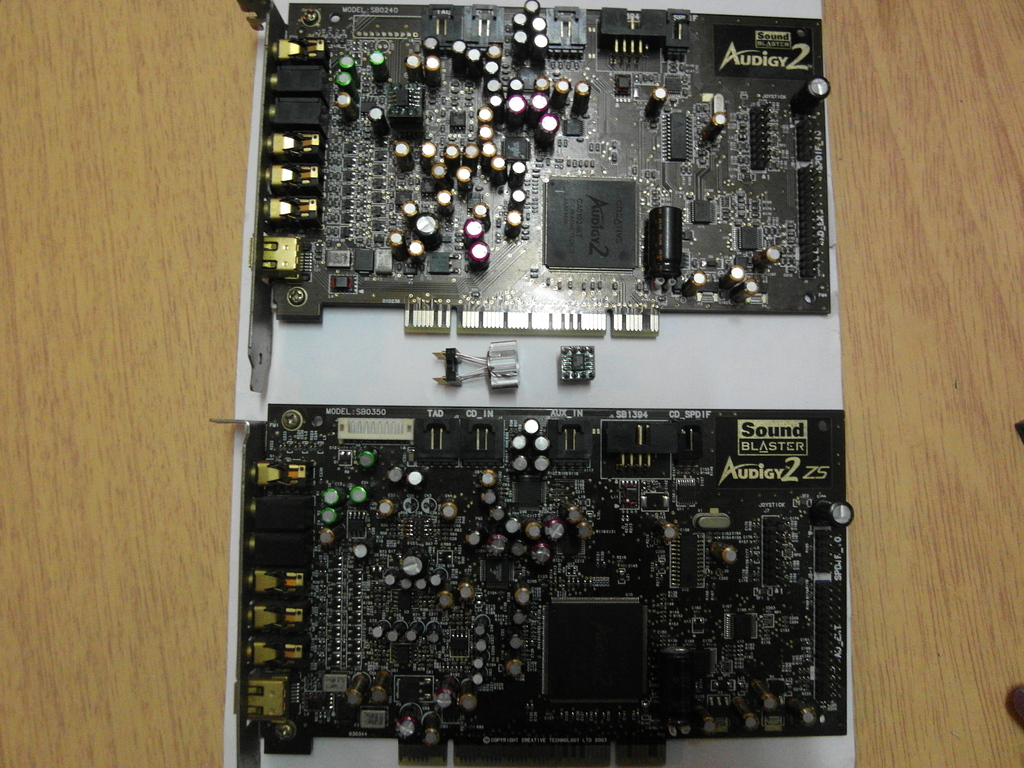
XtremeGamer Fatal1ty Pro (early version)


XtremeGamer Fatal1ty Pro (Same mod a bit differently)


(If you are interested about a modified card like this maybe i can help. Contact: ramachandra@citromail.hu)
Sound Blaster X-Fi Titanium / X-FI Titanium Fatal1ty Pro
My first impression is, this card realy enjoys the benefits provided by the PCI-Express slot. It is already working like an XtremeMusic after some modification. The G-Luxon capacitors on the card are probably better than the Jamicons, but still not Audio grade. So it’s time for an upgrade! The good news for the Fatal1ty Pro owners that, all the mods can be done under the shield.

Compared to the XtremeMusic/XtremeGamer Fatal1ty Pro the design have not changed dramaticly. Or at least not on the part where it needs a modification. Because of this, i don’t need to give the same description about the effect as above.
Update:
The number of capacitors and the way of the polarity on your card maybe not match to mine, look like the Creative made different series. I do not swear but my impression is the cards with more components is the winner.
Update:
Sanyo Os-Con: This ultra durable solid electrolyte capacitors are unbeatable for digital circuits, still using them on the analog section is not advised. The circulating information is somewhat confusing about them, as I figured out the older series with gold plated pins had better sound characteristic. I advise to not follow my example.

Decoupling capacitors: I suggest to use the purple (NOS) Silmic II capacitors. The newer series are maybe better, but the size is problematic, as you can see on the previous pictures. These caps are tested, opened and seems to be genuine Elnas. The legs are not magnetic.
Other caps on the front: They are connected to the DAC, and two of them under the decoupling capacitors to other circuits as well. Use any audio grade caps according to your taste or budget, but to get the best results, stick to the High-End Elnas, Nichicons.
Bypass caps: Added to the 3 capacitors around the DAC and one for the capacitor near the regulator. The suggested ratio is max 1% of the capacitance, but 0.1uF 63V or 100V can do fine.

Oscillator (TCXO): The installation is more or less the same as on the other cards. The output of the osillator needs to be connected to the hole closer to the X-Fi chip. The source of the +5V is the output pin of the regulator near the optical connectors, the GND is the small copper square near the right leg of the crystal. Use a tape on the panel to avoid shorting circuit. The legs can be cut back or bend according to needs.

OpAmps: They can be removed by cutting or desoldering, just like on the photo. I have used 4pcs OPA1602AID without sockets this time. Solder sucker works better for me than desoldering braid to remove excess solder from the pins.

Bypass ower decoupling capacitors: Just an experiment, the results are strongly depend on the quality and value of the used components. If you are interested in playing with it, try MKP, MKS, or lower quality MKT arround 63V-100V. Unfortunaltely the space gives a limit to use something better.
Few useful links to items on eBay: (I hope they will last for a while)
http://www.ebay.com/itm/FINE-LOW-MELT-POINT-FLUXED-SOLDER-WIRE-0-4mm-DIAMETER-6-MTRS-/360452481715?pt=UK_Home_Garden_PowerTools_SM&hash=item53eca462b3
http://www.ebay.com/itm/20pcs-ELNA-SILMIC-Electrolytic-Capacitors-22uF-16V-/320687596301?pt=LH_DefaultDomain_0&hash=item4aaa78630d
http://www.ebay.com/itm/Valab-1PPM-24-5760-MHz-Low-Jitter-Precision-TCXO-/300641150147?pt=LH_DefaultDomain_0&hash=item45ff9be4c3
Titanium HD
I haven’t found any lead how or what to change on the card so i had to try and figure out myself. Im sure there are others who can do these things better and progress further. This is not exactly a guide, best to say that something i have tried. I have only examined the effect on the front speakers, trough the analog and optical connection.

How to change the crystal
Basically the same as on the XtremeMusic with few differences in the connections. The right hole near the X-Fi chip is the place of the output of the oscillator on this card. A good spot for the ground just beside the crystal, the small copper square on the right. In this mod i have decided to get the +5V power from the output of the LM1117 regulator just to do things simple. This way all of the wires and the TCXO remain under the shield. Of course if you do not like the idea to interfere with the job of the regulator, the external powering also can work from a Molex. (red wire +5v, black GND)

The replacement of the capacitors:
So far, the safe way to get rid of the SMT capacitors is to twist them with pliers. I had some other attempts, and ended up with nice damages on the PCB. Desoldering is risky because it requires high temperature and taking too long. If you decide to change capacitors on the card there is a possibility that the shield will not fit on the card any more.

Coupling capacitors: I have used Silver Mica capacitors instead of the other good brand film caps. Micas are cold and agressive, still the best to improve clarity. I have noticed only a tiny improvement after the replacement. Having different values of the capacitors had no further effect on the sound.
Decoupling Capacitors: Elna Silmic II is my best bet as usual, one of the most noticable is the better bass and more comfort for the ears. The 0,1uf 63v polystyrene bypass capacitors can add some small detail to the sound. I had to use both sides of the card to be able to install all the capacitors and two metal film resistors. The original value is 560 Ohm on the card. (i have only 470 Ohm in the photo)
Shortening capacitors also an option, however hardly can be called as an upgrade. The sound was becoming clean but unfortunately flat (poor mid and poorer low range).


Caps around DAC: just a small improvement for the 3D space.

Capacitros for the OpAmps: Not worth to change them alone.
Main capacitor for the X-Fi chip: Hoops! I can not find any. The 47uf capacitor in the bottom right corner is connected to the RAM.
Capacitors near the digital output: After the recap of the whole corner i have noticed significant improvements in the low range sounds on the analog and digital output both. I have tried to play with capacitances, later i have removed all the capacitors, and i heard nothing to support my previous experience. My best guess was that i had a faulty capacitor on my second-hand card. Solid-polymer capacitors have a tendency to fail shortend. (Many time wasted on to upgrade my external DACs so it was not something that i overlooked)
I have to say that the Creative made a big step to use better capacitors on the Titanium HD. The change of the capacitors can bring too small improvements for the sound comparing to the older X-Fi models. Too much pain for a little gain. To verify my experience i bougt another Titanium HD meanwhile to be sure. Probably you figured i did not fall in love with RMAA, just only the sound i can hear, so i gladly sacrificed the shield of the card and used a bit longer wires for better components.
If you are not looking for adventures best bang for the money is to change the OpAmps and the crystal to an ultraprecision clock and be happy.
I have got big inspiration a while ago from Layman's Guide to modify my good old X-Fi. Since I have learnt few things and tricks to improve the X-Fi further more. What I would like to share here is nothing special, most of them well known, but You can save time to read them in one place.
Since X-Fi XtremeMusic, few other soundcards appeared on the market, usually with more extras and better quality. Some can say that: what is the point to upgrade this old outdated modell, it will be never-ever as good as my new shiny 200$ card. If we are loking the technical data they are correct. In reality, this mod can outperform a basic Auzentech X-Fi Forte or Titanium HD card in many ways (I have them both). Even some external DACs as well. It is amazing how much hidden potency remains in this card after many years.
This modification is working on the same way on XtremeMusic and Xtreme Gamer Fatality Pro.
What you need for this upgrade:
Opamps:
4pcs OPA1602AID (for all chanels, no adapters required)
Soldering:
soldering paste (basic is perfect)
soldering iron (narrow head important)
solder (cheap=trouble)
solder sucker
wire cutter
twezers
Clock:
ultra precision 1ppm TCXO 24.576MHz
Capacitors:
16pcs Elna Silmic II 22uf 16V
1pcs Elna Silmic I, II 1500uf 16V or 1000uF 16V
1pcs Elna Silmic I, II, or Cerafine 47uf 16V
3pcs Elna Silmic I, II or Cerafine 10uf 50V
2pcs Elna Silmic I, II, or Cerafine 22uf 16V
1pcs Elna Tonerex 100uf 50V or Silmic II 100uF 25V
6pcs 0.1uf 63V Wima MKS or other brand MKT capacitors
About components:
Opamps:
LM4562: Few years passed, they are better then stock OpAmps but outdated. Very sensitive to noises, what is abundant inside your pc. I have found many of them faulty.
Opa228P: One of the best opamp highly performing in the lower range (bass and drums ect.)
(Thank you Majkel!) The 228p is the mono, 2228p is the stereo version. There are arguments about which one is the better, I personally prefer monos because the less chance for crosstalks. In most cases mono OpAmps are better. The PA series sound brighter than P, and are also good choice.
Opa627AU: have better high but less depth. Very similar to 49710NA (Titanium HD), but Opa627AU is a bit more alive.
Opa637SM: like Opa627AU just in a metal can. One of the best in clarity, instruments really alive, offer less details compared to OPA1602AID.
Opa128SM: Maybe a bit better than Opa638AU
Bursons OpAmp: Some says they are the best, but others have their doubts. (I don't have it yet for testing.)
OPA1602AID: One of the latest OpAmp from the great TI Sound Plus family. Usually OpAmps have a common weakness. Good performance in one or two ranges, and poor or limited in the other(s). This one is without such of weakness. High-End no doubt. (A noticeable thing is a tiny harshness in the midrange. Ears can quickly adapt, not enough to be disappointed) Can be solder directly to the card, no need for adapters.
OPA1612AID: A bit older close enough alternative. Better only on paper than OPA1602AID, sound more neutral in comparison.
Others: There is an ocean of them. Many of them was a great choice for upgrade around 2007 but time is time...
Great threads about OpAmps:
http://www.head-fi.org/t/397691/audio-gd-discrete-op-amps-reviewed-opa-earth-opa-moon-opa-sun-v-2
http://www.diyaudio.com/forums/chip-amps/154106-best-sounding-audio-integrated-opamps.html
Capacitors:
Elnas are one of the best electrolytic capacitors in the audio industry. In this mod they are making the sound clear and warm, easy on the ears, and more realistic 3D! Elnas naturally increase bass, Nichicons are better in the midrange and this is not coming always handy. Other than that, they are great capacitors in the right place and equipment. The difference between the audio grade capacitors and standard is the used materials and technology. Static measurements almost not shows difference in numbers, still the influence undeniably present in the sound. I recommend the following capacitors to use for the modifications:
Elna Silmic II: Most people consider them as the best for audio, warm clean analog sound impressive soundstages and details. A perfect choice for decoupling purpouse.
Elna Silmic: The sound have better body, but less resolution compared to Silmic II. I prefer them over Silmic II if the task is not decoupling.
Elna Cerafine: The closest you can get to the beloved and sometimes overhyped Black gates. Neutral, precise, accurate sound, and not the best choice for decoupling. I love to use them around the DAC chip.
Nichicon KZ: Brilliant midrange and great capacitors for decoupling, but i carefully use them for other purposes because tend to sound flat to my hears. Maybe the size more than problematic.
If no better around still recommended:
Elna Tonerex: Tend to fit to places where the better Elnas do not, cheaper and sound more neutral.
Nichicon FG: Nice rounded sound good midrange and soundstages, lack of bass, smaller size and less clarity than KZ.
Nichicon ES: Excellent choice for decoupling if you love string instruments.
Of course the list can go further but i suggest to not bother with the entry level or what is hard to attain. This links are provide more detailed info about audiograde capacitors:
http://www.head-fi.org/t/528380/electrolytic-capacitors-used-in-audio-dc-blocking-comparison-tread
http://tech.juaneda.com/en/articles/electrolyticcapacitors.html
Ultra precision clock generator (TCXO):
I strongly advice to have on any soundcard. Does not matter how good soundcard you have if a cheap, lazy clock turnig the music to a foggy mess! After the change of crystal the sound becoming crystall clear, all the instruments in place, well separated. It makes the bass tighter. The 0.3ppm oscillators are better than 1ppm for a bit more money.
The mod
(The folloving image is not updated)
Change of capacitors
For soldering caps 60/40 Tin/Lead solder is perfect. The easy way to temove caps is to put some paste & solder to the legs first. Heat up one leg then push the capacitor to one side, then heat the other leg and push to the opposite side, then just repeat. It can ruin the cap, but who cares? To remove old solder from holes is easy if you use the solder sucker on one side, the soldering iron on the other side of the PCB. Some times solder can be really tough to remove from holes, in that case just solder the caps to the surface of the hole. Better option than keep trying and owerheat the SMDs on the card. A wet cloth or tissue can keep the critical areas cold enough from overheating.
A drill could be another option too. But remember to be very careful to select the proper head and not damage the wall of the hole. Even broken legs of the capacitors can be drilled out if necessary.
The negative polarity of electrolyte capacitors are marked on the capacitors and PCB. Using them the opposite way results problems. Film capacitors have no polarity.
Decoupling capacitors: I strongly suggest Silmic II because quality really matters. The 4 capacitors on top belong to the front speaker, the other 12 to the surround speakers. There is one rule for both group: change them all or leave them all!
Caps arround dac: This is a good place for experiments. You can not go wrong with Elna Silmic II alone here, but the same type caps can make the sound signature too strong.
Capacitor for opamps: Elna Tonerex is good for opamps. 50v capacitor is not necessary but higher voltage caps have lover ESR and longer lifetime.
Main capacitor near X-Fi chip: 1000-1500uf is enough, because Elna capacitors are naturally increase bass, and 2200uf way too much after this complete mod.
Extra capacitors: I have taken the idea from a DIY DAC. It gives extra dynamic for the sound, can reveal some hidden details.
The newly installed caps are require minimum 5 days of running to burn in. Before that, expect no miracle.
Installing the clock
To remove the chrystal can look difficult at first. Thanks to the straight legs, the trick is to push out with the head of the soldering iron, then put a screwdriver under and lift carefully.
The card has a crystal what we want to change to an oscillator. The output need to be connected to the left hole on the PCB. And we need energy for the oscillator from an 4 pin extra power connector on the the top right corner. Pin1 +5v, Pin2-3 GND (see little triangle which marks the pin1.) Then connect the floppy power cable to the card for extra juice.
If for some reason the clock doesent work, the windows7 will just be hanging on the loading screen. If it plays the sound too fast or slow, the frequency of the clock is the problem.
Update:
Linux and PCI cards: With the TCXO the there is a good chance Linux operating systems will stuck on boot screen by unknown reason. Better to leave this part of the mod unless you know how to make it work. Use 1000uF capacitor for the main chip instead of 1500-2200F for the full mod, to avoid booming sound.
How to Remove and install OpAmps
Better to do this after the removal of the caps around the OpAmps because there is only small space for work, and this is already the most challenging part of the mod for many who try. Fine low melting point solder wire is great, the cheap low quality can be a headache, or even impossible to solder tiny things with. The first step is to remove the stock OpAmps from the board by cutting of the pins (only one in the time!) and clean the rest. Or add soldering paste, solder the pins together than heat and lift the sides. After finish use alcohol or stain remover + cotton buds to clean off the surface. Throw the old stock OpAmps to the bottom of the bin just to be sure they will be not climbing out
!Soldering paste is a great help to make the solder flow so use plenty on the PCB before soldering the new chips. Start with one pin in the corner than recheck the alignment.
There is one rule about the surround OpAmps: change them all or leave them all. On the front, only one OpAmp is responsible for the left and right channel, on the surround the channels are mixed. I just mention here the sound might be heard quietly if the OpAmp(s) don`t work for some reason. If you are fortunate that is a simple soldering problem (the opposite is shortened, burnt component, damaged PCB, ect..).
Adapters
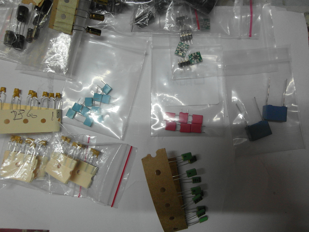
The advantage of using them is obvious if somebody like to have more experience, or simply looking for fun with the sound. The soldered connections is better than plain contacts for audio, so it make sense to stay away from them in the long term. To avoid confusion here is a picture about adapters, and a short descriptions to give an idea what they are. Basically stereo OpAmps can be used on this soundcard, or two mono with adapter(s). By the right adapter different size & package OpAmps working safely. Using a stereo OpAmp in a mono socket or any OpAmp in wrong alignment, is a predictable quick death for the component, so no shame to check the datasheet to be sure and take a second look before the power on. Since they are available on eBay for low cost i do not recommend to spend time on the homemade version.
http://www.ebay.ie/itm/1x-DIP8-SOP8-SOIC8-PCB-adapter-DIP8-SMD-Converter-DIY-/110849802208?pt=LH_DefaultDomain_0&hash=item19cf29bfe0
Making adapters
You need solid core wires, for example Sata cable and 1pcs DIP8 socket for the front and 3 more for surround (gold plated is preferable) First, remove the wires from the Sata cable, and solder 1cm L shape wires to the PCB. Start with the 2. and 4. OpAmp and make the wires short as possible then solder the DIP8 sockets to the wires. After that, use longer wires for the 1. and the 3. If they are at the same level, maybe looking better, but no space for work. The dual to mono adapter is require more space for the front channels, so better if they sitting a bit higher. Extremely important to check all the connections after soldering, because later on it will be very difficult to make corrections, and also there is a high possibility for damage during installation of OpAmps. Epoxy can be used to stabilize the wires if you are 101% sure it is working as expected.
The following picture can be used for troubleshooting. (Sorry, i do not have a proper jack to test side channels).
The alignment of the new opamps is the same as the text on the old ones. Check the marking(s) on the PCB before installation of new socket(s).
Maybe help
Not directly related to the thread, just one of my favorite video how the experts are doing things.
http://www.youtube.com/watch?v=3NN7UGWYmBY
Extra Capacitors
This is at least easy and working pretty good with any 0.1uf film capacitors. Simply solder them to the legs of the capacitors on the back of the card. One goes to the main cap C177 and the other 5 around the DAC chip C91,C119,C108,C56,C107. Ceramic or Tantalum is not great for audio. (I have used Soviet military K73-16 capacitor on the early versions, free from audible external noises. Technical they are superior, unfortunately in size the opposite true.)
Full bypass of muting circuits
What extra you need for this mod:
small size players
magnifying glass (min 40x)
This is a mod what you may or may not like. The removal and the bypass of the muting circuit result more clarity. The advantage brings some disadvantages as well, like hearing the not great quality in music, or the sound is more free flow, but bass is less “kicking” (a bigger cap instead of 1500uf more-less can bring back the balance).
The easy way to get rid of the components on the panel is to twist them left and right with the players. Sometimes they break into pieces, after then just clean the rest with the soldering iron.
35ohm resistors: The bypass will give a tiny improvement for the sound. Maybe some of the connected sound equipment can benefit from that if they are remaining untouched.
Front speakers: The safe way to make the connection is using a bridge-shaped wire.
Surround: Even more simple, you solder the 3 dots together (on the top side of the 6 pin transistors), and remove 46k ohm resistors.
Other tricks
- Removing all of the surround OpAmps can make an improvement if only the two front speakers required. This way the main OpAmp have a better supply of energy, and make an audible difference.
- I suggest to do the change of the caps around the DAC, and install the oscillator in the same time. Because the ultra precision clock will decrease the energy of "vibrant" sounds, the new caps around DAC will increase. They nicely compensate each other.
- Soldering chips to the PCB is risky without a temperature controlled and ESD safe soldering iron. (But not impossible)
- Shortening the decoupling capacitors not really an upgrade for the front speakers. Great for the high range & clarity but significant lose for the low range. After my disappointment on the front speakers i gave a chance for the surround, with good results. I have not experienced any negative side effects like on the front. I suggest to try it out without removing the decoupling caps. Just solder the legs together and listen...
- Soldering together the 1-7-8 pins of the OPA228p making the sound softer.
Drivers
Basically the Creative drivers are stable and reliable, still bugs are exist. The Unofficial Pax drivers are offer a solution, and much more, the installation is simple just like the original. Worth to mention the Pax sound more focused on the midrange and low is set back. If you prefer heavy bass this is not a driver for you no matter analog or digital connection you are using. You can find more details and the drivers here:
http://www.hardwareheaven.com/pax-drivers/
Fix for damaged PCB
Sometimes removing the components are not going well even for experienced modders so good to know what options we have when the damage is done. The surface of the card is covered by a thin layer of paint, what is coming off relatively easy by scratching the surface with a sharp blade or other tool, revealing the real size and way the copper on the surface. It will give the opportunity to have wider surface for soldering or bridge the missing pads. Against oxidation the surface can be covered again with nail-polish if necessary. On the following picture the connections around the OpAmp can be seen.
If the hole of the capacitor damaged a very thin wire can help. Solder one side to the remaining copper and lead to the other side of the hole then install the cap, then ready for soldering as normal. Or use the other side of the PCB and the leg of the component to bridge the missing bit. Maybe not fancy, but electrons don’t care, and easier as well.
Just a bad move and SMD componets have a tendency to breaking off from the panel and not always in one piece. If the necessary value are not available try the closest you can get, or use ordinary (much bigger) 1/4Watt metal film resistors and ceramic capacitors with short legs as possible.
Source of components
What is necessary for this mod can be found on eBay, Mouser, Farnell and approximately costs 40-50€.
I'm only an enthusiastic amateur in electronic, so sorry if i can not provide more scientific approach for this mod.
XtremeGamer Fatal1ty Pro (early version)
XtremeGamer Fatal1ty Pro (Same mod a bit differently)
(If you are interested about a modified card like this maybe i can help. Contact: ramachandra@citromail.hu)
Sound Blaster X-Fi Titanium / X-FI Titanium Fatal1ty Pro
My first impression is, this card realy enjoys the benefits provided by the PCI-Express slot. It is already working like an XtremeMusic after some modification. The G-Luxon capacitors on the card are probably better than the Jamicons, but still not Audio grade. So it’s time for an upgrade! The good news for the Fatal1ty Pro owners that, all the mods can be done under the shield.
Compared to the XtremeMusic/XtremeGamer Fatal1ty Pro the design have not changed dramaticly. Or at least not on the part where it needs a modification. Because of this, i don’t need to give the same description about the effect as above.
Update:
The number of capacitors and the way of the polarity on your card maybe not match to mine, look like the Creative made different series. I do not swear but my impression is the cards with more components is the winner.
Update:
Sanyo Os-Con: This ultra durable solid electrolyte capacitors are unbeatable for digital circuits, still using them on the analog section is not advised. The circulating information is somewhat confusing about them, as I figured out the older series with gold plated pins had better sound characteristic. I advise to not follow my example.
Decoupling capacitors: I suggest to use the purple (NOS) Silmic II capacitors. The newer series are maybe better, but the size is problematic, as you can see on the previous pictures. These caps are tested, opened and seems to be genuine Elnas. The legs are not magnetic.
Other caps on the front: They are connected to the DAC, and two of them under the decoupling capacitors to other circuits as well. Use any audio grade caps according to your taste or budget, but to get the best results, stick to the High-End Elnas, Nichicons.
Bypass caps: Added to the 3 capacitors around the DAC and one for the capacitor near the regulator. The suggested ratio is max 1% of the capacitance, but 0.1uF 63V or 100V can do fine.
Oscillator (TCXO): The installation is more or less the same as on the other cards. The output of the osillator needs to be connected to the hole closer to the X-Fi chip. The source of the +5V is the output pin of the regulator near the optical connectors, the GND is the small copper square near the right leg of the crystal. Use a tape on the panel to avoid shorting circuit. The legs can be cut back or bend according to needs.
OpAmps: They can be removed by cutting or desoldering, just like on the photo. I have used 4pcs OPA1602AID without sockets this time. Solder sucker works better for me than desoldering braid to remove excess solder from the pins.
Bypass ower decoupling capacitors: Just an experiment, the results are strongly depend on the quality and value of the used components. If you are interested in playing with it, try MKP, MKS, or lower quality MKT arround 63V-100V. Unfortunaltely the space gives a limit to use something better.
Few useful links to items on eBay: (I hope they will last for a while)
http://www.ebay.com/itm/FINE-LOW-MELT-POINT-FLUXED-SOLDER-WIRE-0-4mm-DIAMETER-6-MTRS-/360452481715?pt=UK_Home_Garden_PowerTools_SM&hash=item53eca462b3
http://www.ebay.com/itm/20pcs-ELNA-SILMIC-Electrolytic-Capacitors-22uF-16V-/320687596301?pt=LH_DefaultDomain_0&hash=item4aaa78630d
http://www.ebay.com/itm/Valab-1PPM-24-5760-MHz-Low-Jitter-Precision-TCXO-/300641150147?pt=LH_DefaultDomain_0&hash=item45ff9be4c3
Titanium HD
I haven’t found any lead how or what to change on the card so i had to try and figure out myself. Im sure there are others who can do these things better and progress further. This is not exactly a guide, best to say that something i have tried. I have only examined the effect on the front speakers, trough the analog and optical connection.
How to change the crystal
Basically the same as on the XtremeMusic with few differences in the connections. The right hole near the X-Fi chip is the place of the output of the oscillator on this card. A good spot for the ground just beside the crystal, the small copper square on the right. In this mod i have decided to get the +5V power from the output of the LM1117 regulator just to do things simple. This way all of the wires and the TCXO remain under the shield. Of course if you do not like the idea to interfere with the job of the regulator, the external powering also can work from a Molex. (red wire +5v, black GND)
The replacement of the capacitors:
So far, the safe way to get rid of the SMT capacitors is to twist them with pliers. I had some other attempts, and ended up with nice damages on the PCB. Desoldering is risky because it requires high temperature and taking too long. If you decide to change capacitors on the card there is a possibility that the shield will not fit on the card any more.
Coupling capacitors: I have used Silver Mica capacitors instead of the other good brand film caps. Micas are cold and agressive, still the best to improve clarity. I have noticed only a tiny improvement after the replacement. Having different values of the capacitors had no further effect on the sound.
Decoupling Capacitors: Elna Silmic II is my best bet as usual, one of the most noticable is the better bass and more comfort for the ears. The 0,1uf 63v polystyrene bypass capacitors can add some small detail to the sound. I had to use both sides of the card to be able to install all the capacitors and two metal film resistors. The original value is 560 Ohm on the card. (i have only 470 Ohm in the photo)
Shortening capacitors also an option, however hardly can be called as an upgrade. The sound was becoming clean but unfortunately flat (poor mid and poorer low range).
Caps around DAC: just a small improvement for the 3D space.
Capacitros for the OpAmps: Not worth to change them alone.
Main capacitor for the X-Fi chip: Hoops! I can not find any. The 47uf capacitor in the bottom right corner is connected to the RAM.
Capacitors near the digital output: After the recap of the whole corner i have noticed significant improvements in the low range sounds on the analog and digital output both. I have tried to play with capacitances, later i have removed all the capacitors, and i heard nothing to support my previous experience. My best guess was that i had a faulty capacitor on my second-hand card. Solid-polymer capacitors have a tendency to fail shortend. (Many time wasted on to upgrade my external DACs so it was not something that i overlooked)
I have to say that the Creative made a big step to use better capacitors on the Titanium HD. The change of the capacitors can bring too small improvements for the sound comparing to the older X-Fi models. Too much pain for a little gain. To verify my experience i bougt another Titanium HD meanwhile to be sure. Probably you figured i did not fall in love with RMAA, just only the sound i can hear, so i gladly sacrificed the shield of the card and used a bit longer wires for better components.
If you are not looking for adventures best bang for the money is to change the OpAmps and the crystal to an ultraprecision clock and be happy.


 The first 4 capacitors on top belongs to the to the front speakers, the other 12 to the surrounds. I will update the picture & description.


