β24: A discrete, cascoded, fully-differential power amplifier
Feb 18, 2010 at 4:54 PM Post #271 of 309
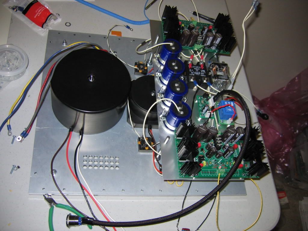
My main motivation is mechanical actually. I was thinking about orienting the trafo vertically and bolting to a 1/4" thick piece of aluminum plate. (The mounting bolt is super beefy so I'm not worried about it... i think it's probably 1/2 or 5/8" diameter.) That plate would have 8 holes in it and would be bolted to the front panel with spacers to allow room for the on/off switch. This way, it can be supported directly by the handles/thick front panel without having to reinforce the bottom panel with a sub chassis or beefing up the brackets that hold the bottom to the heat sinks. This takes the stress off the bolts that hold front panel to the heat sinks as well. Also, I think it would make the front panel a little more interesting to have some large (maybe slightly recessed) socket head caps surrounding the on off switch. There is also a benefit in terms of layout since this reduces the footprint of the trafo. And finally, although there probably isn't much if any impact here, the two trafos would be working on orthogonal axis.
 
Feb 18, 2010 at 5:12 PM Post #272 of 309
one thing to think of is: will the thing be 'heavy as predicted'. ie, people expect the weight to be somewhat even inside a chassis. if you have a real heavy part on one side (a vertical wall) then that unbalances things. when lifting this, it may catch people off guard.

something to think about, perhaps. another facet to product design
wink.gif
 
Feb 18, 2010 at 5:43 PM Post #273 of 309
Quote:

Originally Posted by linuxworks /img/forum/go_quote.gif
one thing to think of is: will the thing be 'heavy as predicted'. ie, people expect the weight to be somewhat even inside a chassis. if you have a real heavy part on one side (a vertical wall) then that unbalances things. when lifting this, it may catch people off guard.

something to think about, perhaps. another facet to product design
wink.gif


I actually have a commercial AVR that is not "heavy as predicted" the tranny sits far to one edge and every time I go to move it I forget about that and always bump the edge of the furniture with it.
 
Feb 18, 2010 at 5:47 PM Post #274 of 309
This will move the CG slightly forward and up. But the CG will still be close to the center of the chassis so I'm not too worried about it. Actually, being closer to the handles themselves might help in this regard and being higher will definitely help.
 
Feb 19, 2010 at 6:29 AM Post #275 of 309
Amb - do the caddock resistors not need any heat sinking at all? I thought I remembered reading that somewhere but that you had used an aluminum spacer to get them to the large heat sink. The standoffs I got will require a pretty thick spacer so I thought I'd just screw the pairs to a piece of aluminum as a little heat sink of their own if that would be sufficient. I could even mill out some grooves to make it more efficient.
 
Feb 19, 2010 at 8:34 AM Post #276 of 309
No, the Caddock resistors do not get hot enough to require heatsinking during normal use. However under bench test conditions they may get warm. Screwing them down on the heatsink takes care of all situations and make them mechanically more secure as well. But no isolation pads or thermal compound is required.
 
Feb 19, 2010 at 5:01 PM Post #278 of 309
Depends on the type of isolation pad you use. If you use the Bergquist Silpads like I did, then you don't need thermal compound. If you use mica pads, then you do.
 
Feb 20, 2010 at 2:47 PM Post #279 of 309
I just sat my traffo in the modushop case and yeah... it already is off the deep-end in terms of ridiculousness size wize.

I have an metric crap-load (SI unit) of PRP here for this as well.
If anything the boards will look pretty.

The scarier part of all of this is that the t2 pcb is essentially the same foot print as the b24 case... What
confused_face_2.gif
 
Mar 29, 2010 at 4:45 AM Post #280 of 309
I finally got my frontpanelexpress hardware and mounted everything up, it's beginning to look like an amp!

My only problem is, I only have the regulated power supplies going at the moment. I tried hooking up my 500VA SumR unit I got for the unregulated power supplies, but with no load on the secondaries, and blew a fuse and tripped my circuit breaker the second time I powered it up (not the first time - very odd
confused.gif
)

After thinking and researching my hypothesis is that the inrush current to the big 500VA transformer might be an issue. My house circuit is 20A and I have a 10A slow-blow in the amp. The whole build is pretty much per AMB's reference build. Does this mean I have to go for broke and set it up per the instructions without even verifying the 500VA unit is outputting the correct secondary voltages? It seems like I must be missing something else here.

Anyway here is a pic, although it probably won't show any detail you might be interested in.

IMG_0368.jpg
 
Mar 29, 2010 at 4:53 AM Post #281 of 309
I don't see why you'd trip the 20A breaker with nothing connected to the trafo. Are you sure you have the primary wired up properly and nothing is shorted on the secondary side?
 
Mar 29, 2010 at 5:09 AM Post #283 of 309
Quote:

Originally Posted by amb /img/forum/go_quote.gif
I don't see why you'd trip the 20A breaker with nothing connected to the trafo. Are you sure you have the primary wired up properly and nothing is shorted on the secondary side?


Yeah I had the 115VAC windings in parallel (not connected to ground) and the 30VAC windings in series with the common node connected to my star ground.

The only thing that I did notice is that I had my 0.5A fuse for the e24 circuit on the neutral line, instead of the hot line, which I have corrected. However I can't see how this would have an effect.

edit: I had my computer running at the time, but as this is well under 10A, I would still have an issue with my 10A fuse.
 
Mar 30, 2010 at 12:27 AM Post #284 of 309
According to my measurements with my crappy DMM, the combined (parallel) DC resistance of the transformer primaries is about 0.5 ohm (0.6 ohm from the big one and about 5 ohm from the smaller one.) When the relay is closed would the AC mains going across this ever "see" this resistance? If so, this is like 192 amps if even for a short period of time. I would think not, since at 60Hz the impedance is probably way different. But I can't think of anything else. I'm convinced that the big trafo is blowing the fuse, and I'm also convinced I have everything wired correctly.
 
Mar 30, 2010 at 6:39 AM Post #285 of 309
If your circuit is unloaded <scratches head>, as Amb stated you must have something wired wrong or maybe there is a winding shorted in the trafo(not likely on new ones however). There shouldn't be any reason not to just get the PS working first. Build quality looks impeccable. Good Luck and I'm hoping you find the solution soon.
 

Users who are viewing this thread

Back
Top