I have created a JavaScript webpage calculator and Excel spreadsheet that will help you optimize a headphone resistor network interface for your headphones and your speaker amplifier.


The headphone cable's shield carries the combined common ground negative signal.
I added resistor network power and current calculations to the Headphone Resistor Network Calculator spreadsheet. You input the amplifier output voltage and the spreadsheet shows amp power and current output and what actually flows through the headphones. Click on the pic for a clearer view.

Before building a headphone network interface I recommend you connect your headphones directly to the speaker amp and listen. Here's how to make a balanced headphone-to-speaker-amp adapter cable or see this page to make a single-ended headphone adapter cable. Make sure the amp is off or unplugged as you connect the headphones and turn the volume completely down before turning on your amp. Then slowly turn up the volume. Many amps will sound great without an interface.
Because headphones are so sensitive you can sometimes hear amplifier noise floor hiss when connected direct. Also sometimes you'll end up with only being able to turn your amp up just a little before the volume is too loud. This resistor network interface can solve the hiss and volume knob problem by adding attenuation to bypass some of the amp's output power. The hiss will be less noticeable and you'll have more useable volume knob movement to adjust your listening level.
Most solid state (non-tube) amplifiers will have no problem driving headphones of any impedance so you can add attenuation by simply adding a resistor to each stereo channel's positive wire (no need for Resistor 3). Typically a 50 to 100 ohm 3 watt resistor will do the trick.
The advantage of using the headphone resistor network on this page is that it will add attenuation and also give your amp the speaker load it was designed for. This can be especially critical with tube amplifiers that use output transformers. If you build the network interface shown on this page it will work with almost all amplifiers, tube or solid state.
Here's the link to the webpage headphone resistor network calculator.
Download my much more detailed Excel spreadsheet Headphone Resistor Network Calculator The instructions are on page 2 of the spreadsheet but operation is similar to the webpage calculator.
I built my Headphone Resistor Network Interface using these resistors:
Vishay/Dale wirewound non-inductive resistors. The exact parts from Mouser.com were:
Mouser part# 71-RS0056R000FB12 Vishay part# RS0056R000FB12 5watts 6ohms 1%
Mouser part# 71-NS2B-2 Vishay part# NS02B2R000FB12 3watts 2ohms 1%
The resistors were about $2 each with $5 shipping.
EfSpeakLoad = Effective Speaker Load
EfHPOut = Effective HeadPhone Output impedance
HeadImp = rated Headphone Impedance
AmpOut = Amp Output impedance (usually < 0.1)
ResX = Resistor
I want to thank the Head-Fi'ers and specifically Chris J and Armaegis for their help creating these tools. I hope you find them useful

Instructions
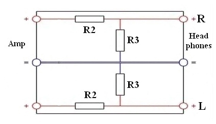
A headphone resistor network interface helps to electrically match a pair of headphones to a speaker amplifier's speaker terminals. The resistor network used on this page is the most commonly recommended headphone-to-speaker-amp resistor network interface.
1. Input your Headphone's Impedance rating, your Amplifier's Speaker Load rating (usually 4 or 8 ohms) and the Amp's Output Impedance (if you don't know leave it at 0.1).
2. Click the "Calculate" button3. A Resistor2 value of 6 ohms and Resistor3 value of 2 ohms will be close to optimal for most headphones and speaker amps but be sure and play around with the value of Resistor2 and Resistor3 and recalculate to see what happens. The goal is to match your Effective Speaker Load with your amp's speaker load rating (usually 8 ohms). You should also try to maintain a 3 to 1 ratio for the R2 to R3 values, i.e., if Resistor2=6 then Resistor3 should be approximately 2. The greater the ratio between Resistor2 and Resistor3 the higher the Amp Attenuation. Resistor 1 should be rated at 5 watts and Resistor 2 should be rated at 3 watts. Both should be 1%, wire wound, non-inductive Resistors.
4. The Amp Attenuation value is used to indicate how much of your amp's power will bypass your headphones and lower its output. The higher the Amp Attenuation the lower the amp's output and the more the volume knob will have to turn. More Attenuation can help reduce the amp's noise floor hiss that can sometimes be heard using headphones with powerful speaker amps and give you more useable volume knob movement.
This network interface can be used with balanced or unbalanced (single-ended) headphones. If you do plan to use this network interface with single-ended headphones make sure your amplifier has the two black speaker terminals tied together. Unplug your amp and use a multimeter's continuity function and touch the two probes to the black speaker terminals and listen for the continuity beep. If the two black speaker terminals are not tied together (no beep) do not connect unbalanced (single-ended) headphones to it or you may damage or destroy the amp.
Single-Ended Headphone Network
The headphone cable's shield carries the combined common ground negative signal.
I added resistor network power and current calculations to the Headphone Resistor Network Calculator spreadsheet. You input the amplifier output voltage and the spreadsheet shows amp power and current output and what actually flows through the headphones. Click on the pic for a clearer view.

Before building a headphone network interface I recommend you connect your headphones directly to the speaker amp and listen. Here's how to make a balanced headphone-to-speaker-amp adapter cable or see this page to make a single-ended headphone adapter cable. Make sure the amp is off or unplugged as you connect the headphones and turn the volume completely down before turning on your amp. Then slowly turn up the volume. Many amps will sound great without an interface.
Because headphones are so sensitive you can sometimes hear amplifier noise floor hiss when connected direct. Also sometimes you'll end up with only being able to turn your amp up just a little before the volume is too loud. This resistor network interface can solve the hiss and volume knob problem by adding attenuation to bypass some of the amp's output power. The hiss will be less noticeable and you'll have more useable volume knob movement to adjust your listening level.
Most solid state (non-tube) amplifiers will have no problem driving headphones of any impedance so you can add attenuation by simply adding a resistor to each stereo channel's positive wire (no need for Resistor 3). Typically a 50 to 100 ohm 3 watt resistor will do the trick.
The advantage of using the headphone resistor network on this page is that it will add attenuation and also give your amp the speaker load it was designed for. This can be especially critical with tube amplifiers that use output transformers. If you build the network interface shown on this page it will work with almost all amplifiers, tube or solid state.
Here's the link to the webpage headphone resistor network calculator.
Download my much more detailed Excel spreadsheet Headphone Resistor Network Calculator The instructions are on page 2 of the spreadsheet but operation is similar to the webpage calculator.
I built my Headphone Resistor Network Interface using these resistors:
Vishay/Dale wirewound non-inductive resistors. The exact parts from Mouser.com were:
Mouser part# 71-RS0056R000FB12 Vishay part# RS0056R000FB12 5watts 6ohms 1%
Mouser part# 71-NS2B-2 Vishay part# NS02B2R000FB12 3watts 2ohms 1%
The resistors were about $2 each with $5 shipping.
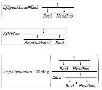
Formulas Used
EfSpeakLoad = Effective Speaker Load
EfHPOut = Effective HeadPhone Output impedance
HeadImp = rated Headphone Impedance
AmpOut = Amp Output impedance (usually < 0.1)
ResX = Resistor
I want to thank the Head-Fi'ers and specifically Chris J and Armaegis for their help creating these tools. I hope you find them useful
