Impedance Adapters/Cables | Explained & Listed
Mar 25, 2012 at 11:11 AM Post #16 of 157
Quote:
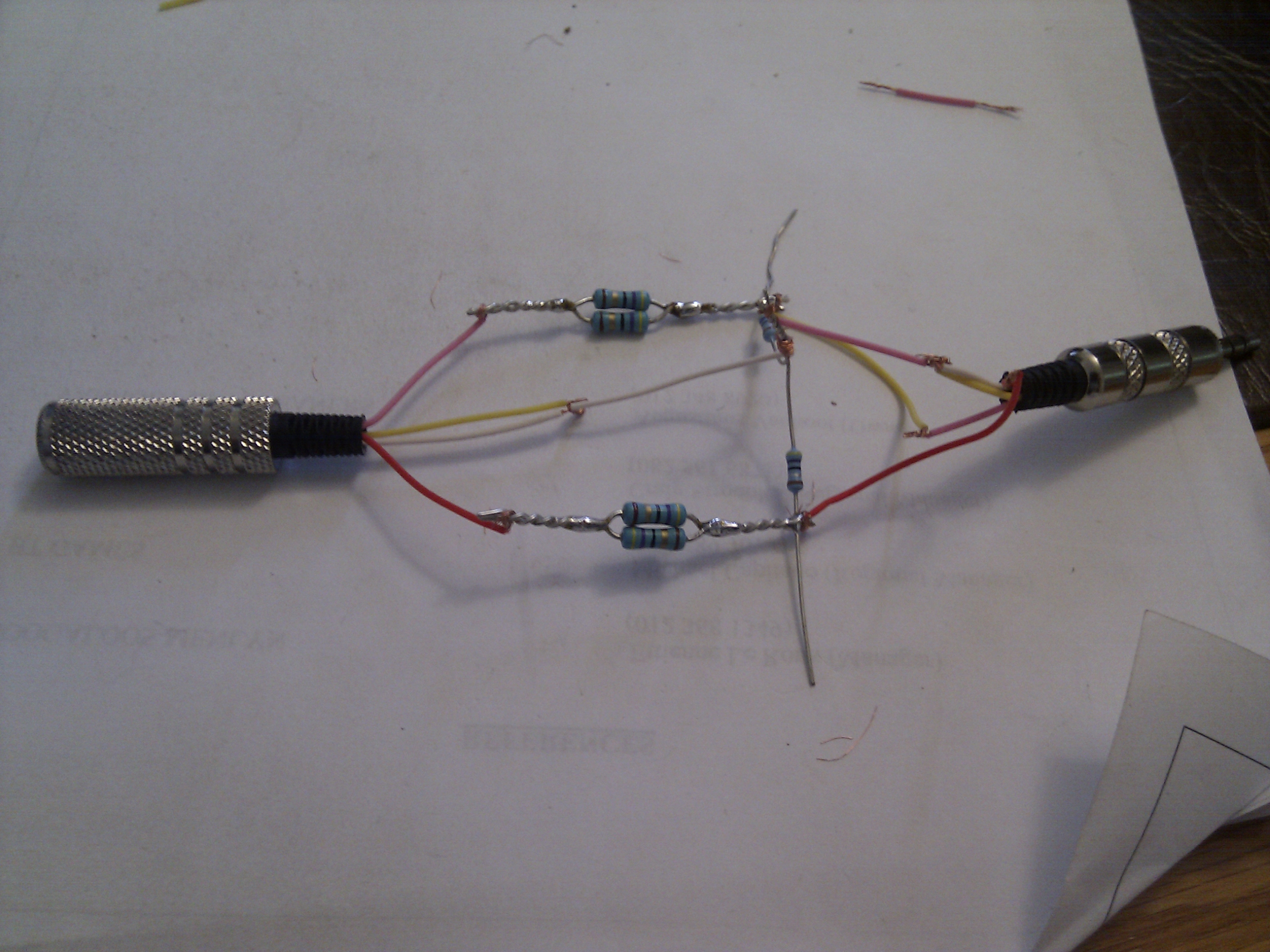
I think you mean you can use MORE sensitive IEMs with your high gain desktop amp.
This is because the resistive network will decrease the apparent gain of the headphone amp


fixed
 
 
Mar 25, 2012 at 11:50 AM Post #17 of 157


Quote:
 
I have already explained this, but you are wrong. If you still do not believe, here is a simple test with a source that has 100 Ohm output impedance, and a 250 Ohm headphone. The left channel was connected directly to the headphone, but its level was reduced by 20 dB. On the right channel, I used a 680 Ohm potentiometer as a serial resistor, and a 27 Ohm parallel resistor. I adjusted the potentiometer so that the levels were matched. At that setting (~220 Ohm), the source "saw" a roughly similar impedance load on both channels. I have then created a frequency response and 40 Hz distortion graph, recording the voltage from the headphone. The result is:
   
As you can see, the frequency response is nicely flattened out, and the THD is reduced by a factor of about 4. This is consistent with what would be expected from an output impedance reduction from 100 Ohm to 25 Ohm.


Your reply is a bit rude.
 
We agree that adding a 220 resistor reduces gain and reduces efficiency.
 
You haven't listed you headphone amplifier (or source) or your headphone.
What you have proven that adding a 27 ohm damping resistor in parallel with the headphone adds damping, therefore decreasing distortion. It is not the optimum damping value for every headphone.  Some headphones don't even require damping.
You have also proven that adding a 27 ohm resistor in parallel with that headphone swamps out the effects of the impedance of the headphone (assuming the impedance varies with frequency) therefore smoothing out the frequecy response.
You have proven that your resistive network mitigates the frequency and damping effects of high output impedance on that headphone, but you can't make the actual output impedance go away by adding more series and parallel resistance.


Mar 25, 2012 at 12:46 PM Post #18 of 157
Quote:
Originally Posted by Chris J /img/forum/go_quote.gif
 
You have proven that your resistive network mitigates the frequency and damping effects of high output impedance on that headphone, but you can't make the actual output impedance go away by adding more series and parallel resistance.


It depends on your definition of "output impedance", but you cannot deny that the resistor network achieves the same effect of increased electrical damping as a lower output impedance. And the output jack of the adapter (to which the headphones are connected) does have the lower output impedance - ~25 Ohm in this particular case - if I measure it as if it was the output of an amplifier.
 
 
Mar 25, 2012 at 1:02 PM Post #19 of 157
Quote:
It depends on your definition of "output impedance", but you cannot deny that the resistor network achieves the same effect of increased electrical damping as a lower output impedance. And the output jack of the adapter (to which the headphones are connected) does have the lower output impedance - ~25 Ohm in this particular case - if I measure it as if it was the output of an amplifier.


Mmm so your stating that in my case with the d2k it will be a 20 or 24 ohm resistor, but with different headphones it will increase?
interesting, what would be the rule of thumb regarding what those values should be taking into account output impedance and headphone impedance.
 
EDIT: Please dont let this turn into an argument, you both have valid points
 
Mar 25, 2012 at 3:04 PM Post #20 of 157
Quote:
Mmm so your stating that in my case with the d2k it will be a 20 or 24 ohm resistor, but with different headphones it will increase?

 
Yes, the choice of resistors depends on the headphones, but also on the source. Basically, the following need to be taken into account to find a good trade-off:
  - the intended effective output impedance (depends on the headphones)
  - the sensitivity of the adapter+headphone combination (i.e. the source should still be able to power it adequately)
  - the impedance of the adapter+headphone combination (should not be too low)
 
 
Mar 25, 2012 at 3:34 PM Post #21 of 157
Quote:
 
Yes, the choice of resistors depends on the headphones, but also on the source. Basically, the following need to be taken into account to find a good trade-off:
  - the intended effective output impedance (depends on the headphones)
  - the sensitivity of the adapter+headphone combination (i.e. the source should still be able to power it adequately)
  - the impedance of the adapter+headphone combination (should not be too low)


Good to note.
Ill update the main post now now.
I'm about to ask a big favour :p
 
An idiots equation. Since many people reading this will probably not understand all the electrical stuff.
 
So can come up with a basic enough enough equation that anyone can come here and find out what they need.
 
 
Mar 25, 2012 at 11:08 PM Post #22 of 157


Quote:
It depends on your definition of "output impedance", but you cannot deny that the resistor network achieves the same effect of increased electrical damping as a lower output impedance. And the output jack of the adapter (to which the headphones are connected) does have the lower output impedance - ~25 Ohm in this particular case - if I measure it as if it was the output of an amplifier.


I just agreed with you that the resistive network achieves the same effect as a lower output impedance.
You're not the first guy to conduct an experiment, get some very good data, and draw an erroneous conclusion.
Obviously you think I'm an idiot, I have no idea what I am talking about, so I'm outta here.  


Mar 26, 2012 at 4:49 AM Post #23 of 157
Quote:
I just agreed with you that the resistive network achieves the same effect as a lower output impedance.
You're not the first guy to conduct an experiment, get some very good data, and draw an erroneous conclusion.
Obviously you think I'm an idiot, I have no idea what I am talking about, so I'm outta here. 


Really? I think thats a bit childish, just calm down, and logically prove your point. With facts, links , equations or whatever, but nothing gets sorted by throwing a tantrum and leaving.
 
 
Mar 26, 2012 at 6:31 AM Post #24 of 157
Quote:
Originally Posted by Chris J /img/forum/go_quote.gif
 
You're not the first guy to conduct an experiment, get some very good data, and draw an erroneous conclusion.

 
I did not draw the conclusion from the experiment. I did the experiment to demonstrate that the theory is correct (of which I was already 100% sure), and that it achieves the intended effect in practice.
 
 
Mar 27, 2012 at 7:48 PM Post #25 of 157


I did not draw the conclusion from the experiment. I did the experiment to demonstrate that the theory is correct (of which I was already 100% sure), and that it achieves the intended effect in practice.


I am not disputing your theory outright. Just one small point. To recap: Your theory was that if you add a DAMPING resistor across the headphone it may be possible to compensate for the very low DAMPING FACTOR you are seeing from your 100 ohm source and your 250 ohm headphone combination. Since you have added a damping resistor across the headphone you have done two things: 1. reduced the distortion. 2. flattened out the voltage applied across the headphone. This would be even more pronounced with headphones having wild impedance swings across the audio badwidth. The 27 ohm resistor swamps out any impedance variations you may have in your headphone. So in practice it acheives the intended effect. It is a very fine point I am making: the amp output impedance is now 100 + 220 ohms = 320 ohms. i.e. add the original source impedance to the impedance of the resistor in series with the load. This is the definition of output impedance. One way you can see this because you had to reduce the gain of the other channel by 20 dB to match the losses in the channel with the resistor network. Please note that I am NOT disputing your results! I am only disputing one minor point! That point is: have you reduced output impedance? No. The experiment answers a VERY interesting question: can you compensate for a high output impedance with a resistive network? If you are referring to damping factor then, Yes! If you want to reduce the frequency variations caused by the high output impedance then you can also do this. This is NOT a simple subject by any means. YMMV with other headphones and other resistor values. But the network causes losses so you had to reduce the gain of the other channel by 20 dB.
 
Mar 27, 2012 at 10:26 PM Post #26 of 157


Quote:
It is a very fine point I am making: the amp output impedance is now 100 + 220 ohms = 320 ohms.i.e. add the original source impedance to the impedance of the resistor in series with the load.This is the definition of output impedance.

 
That's incorrect.
 
If the amplifier's output impedance is 100 ohms, and you shunt that with a 220 ohm resistor, then the amplifier's effective output impedance isn't the series combination of those two values but rather the parallel combination of those two values, or 68.75 ohms, not 320 ohms.
 
And as for lowering distortion, the amplifier will see the parallel combination of the 220 ohm resistor and the 250 ohm headphones, which would be 117 ohms, instead of the 250 ohms it would see otherwise. So now the amplifier has a somewhat heavier load to drive and all else being equal, distortion will tend to increase.
 
se


Mar 27, 2012 at 10:28 PM Post #27 of 157


Quote:
 
That's incorrect.
 
If the amplifier's output impedance is 100 ohms, and you shunt that with a 220 ohm resistor, then the amplifier's effective output impedance isn't the series combination of those two values but rather the parallel combination of those two values, or 68.75 ohms, not 320 ohms.
 
And as for lowering distortion, the amplifier will see the parallel combination of the 220 ohm resistor and the 250 ohm headphones, which would be 117 ohms, instead of the 250 ohms it would see otherwise. So now the amplifier has a somewhat heavier load to drive and all else being equal, distortion will tend to increase.
 
se


Not even close.............
 
 
Mar 27, 2012 at 10:45 PM Post #28 of 157


Quote:
Not even close.............


No, it's quite spot on.
 
If you have an amplifier with a 100 ohm output impedance, and across that amplifier's output you add a 220 ohm resistor, the output impedance as seen by the load is the parallel combination of those two values.
 
You need to brush up on basic circuit analysis. Remember, in the Thevenin analysis, voltage sources are shorted. That places the amplifier's 100 ohm output impedance in parallel with the 220 ohm resistor across the amplifier's output, not in series with it. So looking into the amplifier's output, you see 68.75 ohms, not 320 ohms. And 68.75 ohms is lower than the amplifier's 100 ohm output impedance.
 
se
 
Mar 27, 2012 at 11:07 PM Post #29 of 157


Quote:
No, it's quite spot on.
 
If you have an amplifier with a 100 ohm output impedance, and across that amplifier's output you add a 220 ohm resistor, the output impedance as seen by the load is the parallel combination of those two values.
 
You need to brush up on basic circuit analysis. Remember, in the Thevenin analysis, voltage sources are shorted. That places the amplifier's 100 ohm output impedance in parallel with the 220 ohm resistor across the amplifier's output, not in series with it. So looking into the amplifier's output, you see 68.75 ohms, not 320 ohms. And 68.75 ohms is lower than the amplifier's 100 ohm output impedance.
 
se


You are grossly misapplying Thevinin's Theorem.
Read the thread again.
Read up on Thevenin again.
STV took a source with a 100 ohm output impedance.
Then he added a 220 ohm resistor in series with the load.
100 + 220 = 320 ohms.
The load is a 250 ohm 'phone in parallel with a 27 ohm resistor.
Thevenin's Theorem does not apply as the "black box" (i.e his source) has only one Voltage source and a defined output impedance of 100 ohms. 
Like I said, from the load's point of view the output terminals are across the parallel combination of the headphone and the 27 ohm resistor. 
 
 
Mar 27, 2012 at 11:21 PM Post #30 of 157


Quote:
Originally Posted by Chris J /img/forum/go_quote.gif
 
Then he added a 220 ohm resistor in series with the load.


Ok. You'd said "Since you have added a damping resistor across the headphone you have done two things..." I thought you meant it was the 220 ohm resistor across the headphones. Sorry.
 
Quote:
The load is a 250 ohm 'phone in parallel with a 27 ohm resistor.

 
Ok. So if he's got a 27 ohm resistor in parallel with the headphones, that means it's also across the amplifier's output. So the effective output impedance of the amplifier, i.e. the source impedance seen by the headphones, will be much lower still.
 
Quote:
Like I said, from the load's point of view the output terminals are across the parallel combination of the headphone and the 27 ohm resistor.

 
If we consider the headphone to be the load, then the headphone is effectively seeing an amplifier with an output impedance of about 25 ohms, i.e. 100 + 220 in parallel with 27.
 
se


Users who are viewing this thread

Back
Top